Invacare TDXSP Owners Manual 3 - Page 34
Description
 |
View all Invacare TDXSP manuals
Add to My Manuals
Save this manual to your list of manuals |
Page 34 highlights
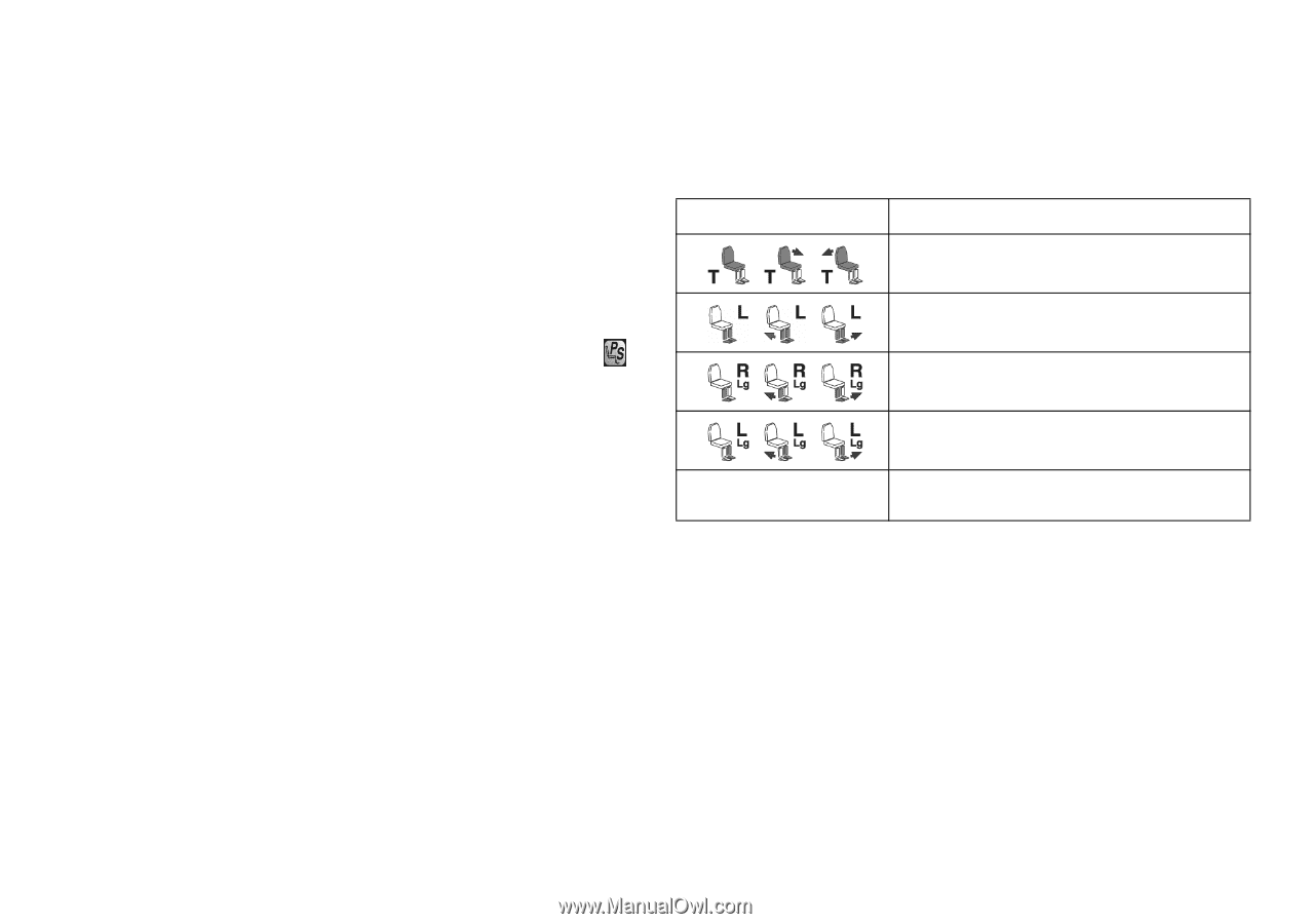
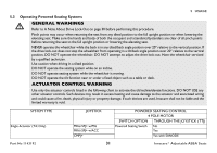
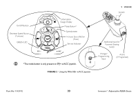
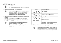
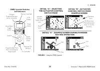
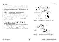
5 USAGE Using the CMPJ+ Joystick For this procedure, refer to FIGURE 3 on page 35. 1. Make sure the wheelchair is on a level surface. The drive select toggle switch is located on the left side, below the LCD. The drive select position is momentary, meaning that it will return to the neutral position after a selection is made. 2. Select a drive that has the Actuator Control Switch Mode icon displayed. 3. Select the Actuator Control Switch Mode icon (Detail "A"). 4. Four of the following icons will display when Actuator Control Switch Mode is selected: The location of the icons indicates the joystick direction or quadrant (Detail "B"). The three icons indicate up/down, up or down, respectively. ICON DESCRIPTION Tilt Operations Combined Power Leg Operations Right Leg Operations Left Leg Operations No powered seating operation has been programmed for this quadrant. 5. Select the desired operation using the joystick or an equivalent switch. While operating the powered seating system, the selected icon will display on the screen along with text indicating the current operation (Detail "C"). Invacare® Adjustable ASBA Seats 34 Part No 1143192
-
 1
1 -
2
-
3
-
4
-
5
-
6
-
7
-
8
-
9
-
10
-
11
-
12
-
13
-
14
-
15
-
16
-
17
-
18
-
19
-
20
-
21
-
22
-
23
-
24
-
25
-
26
-
27
-
28
-
 29
29 -
 30
30 -
 31
31 -
 32
32 -
 33
33 -
 34
34 -
 35
35 -
 36
36 -
 37
37 -
 38
38 -
 39
39 -
40
-
41
-
42
-
43
-
44
-
45
-
46
-
47
-
48
-
49
-
50
-
51
-
52
-
53
-
54
-
55
-
56
-
57
-
58
-
59
-
60
-
61
-
62
-
63
-
64
-
65
-
66
-
67
-
68
-
69
-
70
-
71
-
72
-
73
-
74
-
75
-
76
-
77
-
78
-
79
-
80
 |
 |