Invacare TDXSP Owners Manual 3 - Page 59
Adjusting the Tension of the Flip Up Footplate, Adjusting the Angle of the Cantilever Arm
 |
View all Invacare TDXSP manuals
Add to My Manuals
Save this manual to your list of manuals |
Page 59 highlights
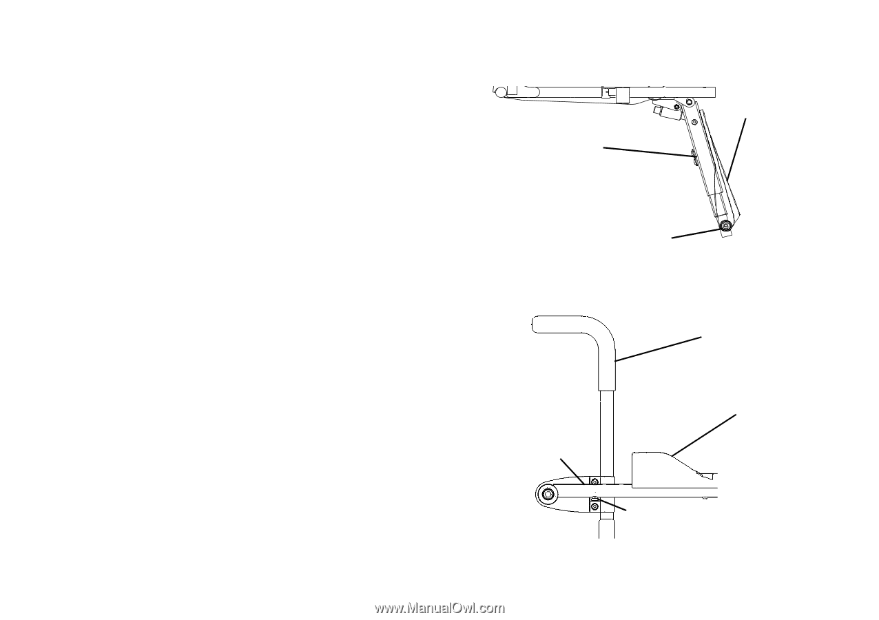
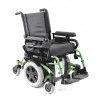
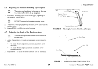
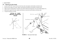
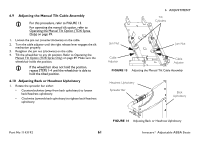
6.6 Adjusting the Tension of the Flip Up Footplate The tension can be adjusted to increase or decrease the rotation effort of the flip up footplates. 1. Loosen the mounting screw on the front rigging angle hinge to decrease the rotation effort. DO NOT remove the footplate mounting screw. 2. Tighten the front rigging angle hinge mounting screw to increase the rotation effort. 3. Repeat STEPS 1 and 2 for the other footplate. 6.7 Adjusting the Angle of the Cantilever Arm Access to the adjustment screw is on the bottom of the arm tube. 1. Adjust the cantilever arm angle as necessary to accommodate the user. • To adjust the arm angle down, turn the adjustment screw clockwise. • To adjust the arm angle up, turn the adjustment screw counterclockwise. 2. Repeat STEP 1 to adjust the other cantilever arm (as necessary). Center Mount Front Rigging 6 ADJUSTMENT Footplate Mounting Screw FIGURE 10 Adjusting the Tension of the Flip Up Footplate Back Cane Arm Tube Arm Pad Part No 1143192 Adjustment Screw FIGURE 11 Adjusting the Angle of the Cantilever Arm 59 Invacare® Adjustable ASBA Seats
-
 1
1 -
2
-
3
-
4
-
5
-
6
-
7
-
8
-
9
-
10
-
11
-
12
-
13
-
14
-
15
-
16
-
17
-
18
-
19
-
20
-
21
-
22
-
23
-
24
-
25
-
26
-
27
-
28
-
29
-
30
-
31
-
32
-
33
-
34
-
35
-
36
-
37
-
38
-
39
-
40
-
41
-
42
-
43
-
44
-
45
-
46
-
47
-
48
-
49
-
50
-
51
-
52
-
53
-
 54
54 -
 55
55 -
 56
56 -
 57
57 -
 58
58 -
 59
59 -
 60
60 -
 61
61 -
 62
62 -
 63
63 -
 64
64 -
65
-
66
-
67
-
68
-
69
-
70
-
71
-
72
-
73
-
74
-
75
-
76
-
77
-
78
-
79
-
80
 |
 |