Invacare TDXSP Owners Manual 3 - Page 67
SETUP/MAINTENANCE, Part No 1143192, Invacare® Adjustable ASBA Seats
 |
View all Invacare TDXSP manuals
Add to My Manuals
Save this manual to your list of manuals |
Page 67 highlights
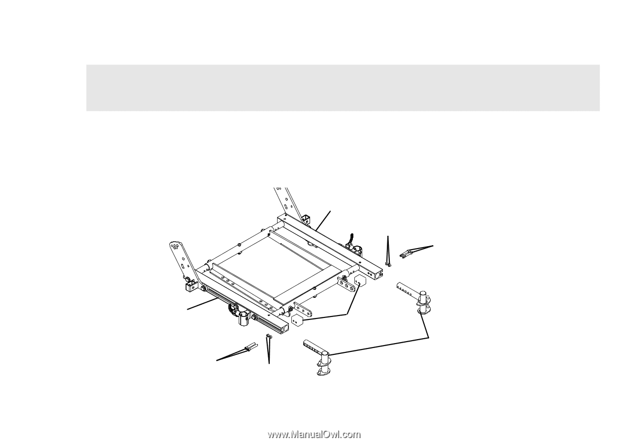
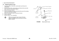
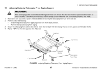
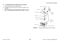
7.5 Adjusting/Replacing Telescoping Front Rigging Support 7 SETUP/MAINTENANCE ƽ WARNING If the telescoping tubes need to be extended greater than two inches, then the seat must be repositioned rearward to ensure stability - otherwise personal injury and/or damage to the wheelchair and surrounding property may result. 1. Remove the two cap screws, spacers and threaded blocks securing the telescoping front tube to the side rail. 2. Perform one of the following: • Slide existing telescoping front rigging support to one of six depth positions. • Remove existing telescoping front rigging. 3. Secure the telescoping front tube to the side rail at the desired depth with the existing two cap screws, spacers and threaded blocks. 4. Repeat STEPS 1 to 3 on the opposite side, if desired. Side Rail Spacers Cap Screws Part No 1143192 Side Rail Cap Screws Spacers Threaded Blocks Telescoping Front Tube FIGURE 2 Adjusting/Replacing Telescoping Front Rigging Support 67 Invacare® Adjustable ASBA Seats
-
 1
1 -
2
-
3
-
4
-
5
-
6
-
7
-
8
-
9
-
10
-
11
-
12
-
13
-
14
-
15
-
16
-
17
-
18
-
19
-
20
-
21
-
22
-
23
-
24
-
25
-
26
-
27
-
28
-
29
-
30
-
31
-
32
-
33
-
34
-
35
-
36
-
37
-
38
-
39
-
40
-
41
-
42
-
43
-
44
-
45
-
46
-
47
-
48
-
49
-
50
-
51
-
52
-
53
-
54
-
55
-
56
-
57
-
58
-
59
-
60
-
61
-
 62
62 -
 63
63 -
 64
64 -
 65
65 -
 66
66 -
 67
67 -
 68
68 -
 69
69 -
 70
70 -
 71
71 -
 72
72 -
73
-
74
-
75
-
76
-
77
-
78
-
79
-
80
 |
 |