Invacare TDXSP2V Owners Manual - Page 70
Removing/Installing the Shrouds
 |
View all Invacare TDXSP2V manuals
Add to My Manuals
Save this manual to your list of manuals |
Page 70 highlights
Invacare® TDX® SP2 Series 9.6 Removing/Installing the Shrouds CAUTION! - Place the wheelchair in a well ventilated area where work can be performed without risking damage to carpeting or floor covering. 9.6.1 Removing/Installing the Rear Shroud Installing the Rear Shroud 1. Install the rear shroud B and secure in place with knob screw A. 9.6.2 Removing/Installing the Front Shroud Fig. 9-1 Removing the Rear Shroud 1. Verify the joystick On/Off switch is in the Off position. 2. Remove the knob screw A that secures the rear shroud B to the base frame C. 3. Remove the rear shroud from the base frame. 70 Fig. 9-2 Removing 1. Remove the front riggings. 2. Remove the knobs D securing the front shroud to the battery box E. Installing 60101877-B
-
 1
1 -
2
-
3
-
4
-
5
-
6
-
7
-
8
-
9
-
10
-
11
-
12
-
13
-
14
-
15
-
16
-
17
-
18
-
19
-
20
-
21
-
22
-
23
-
24
-
25
-
26
-
27
-
28
-
29
-
30
-
31
-
32
-
33
-
34
-
35
-
36
-
37
-
38
-
39
-
40
-
41
-
42
-
43
-
44
-
45
-
46
-
47
-
48
-
49
-
50
-
51
-
52
-
53
-
54
-
55
-
56
-
57
-
58
-
59
-
60
-
61
-
62
-
63
-
64
-
 65
65 -
 66
66 -
 67
67 -
 68
68 -
 69
69 -
 70
70 -
 71
71 -
 72
72 -
 73
73 -
 74
74 -
 75
75 -
76
-
77
-
78
-
79
-
80
-
81
-
82
-
83
-
84
-
85
-
86
-
87
-
88
 |
 |

Invacare® TDX® SP2 Series
9.6
Removing/Installing the Shrouds
CAUTION!
– Place the wheelchair in a well ventilated area
where work can be performed without risking
damage to carpeting or floor covering.
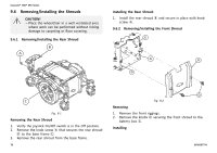
9.6.1
Removing/Installing the Rear Shroud
Fig. 9-1
Removing the Rear Shroud
1.
Verify the joystick On/Off switch is in the Off position.
2.
Remove the knob screw
A
that secures the rear shroud
B
to the base frame
C
.
3.
Remove the rear shroud from the base frame.
Installing the Rear Shroud
1.
Install the rear shroud
B
and secure in place with knob
screw
A
.
9.6.2
Removing/Installing the Front Shroud
Fig. 9-2
Removing
1.
Remove the front riggings.
2.
Remove the knobs
D
securing the front shroud to the
battery box
E
.
Installing
70
60101877-B