JET Tools JWP-15HH User Manual - Page 11
Adjustments
 |
View all JET Tools JWP-15HH manuals
Add to My Manuals
Save this manual to your list of manuals |
Page 11 highlights
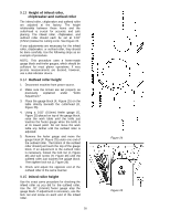
9.0 Adjustments Disconnect machine from power source before making adjustments (except feed rate). 9.1 Belt tension Inspect the tension of the belts frequently during the first few times you use the planer. Belts often stretch during this trial period. If they require tightening, proceed as follows: 1. Remove the belt guard and the rear panel. 2. Loosen the bottom nut on the motor adjustment screw (Figure 11) with a 17mm wrench. 3. Turn the top nut on the adjustment screw to lower the motor plate, which will increase the belt tension. 4. Proper tension is achieved when there is slight deflection in the belt midway between the pulleys, using moderate finger pressure. 5. Tighten the bottom nut on the adjustment screw (Figure 11). 9.2 Pulley alignment The pulleys should be in line for proper belt operation. 1. Remove the belt guard and place a straight edge against the faces of both pulleys (Figure 12). 2. If the straight edge does not lie flat on both pulley faces, as shown in Figure 13, open the rear panel and loosen the four hex nuts on the motor plate (these are shown in Figure 11) with a 12mm wrench. 3. Nudge the motor left or right until the pulleys are in alignment. 4. Tighten hex nuts and replace covers. Figure 11 Figure 12 Figure 13 11
-
 1
1 -
2
-
3
-
4
-
5
-
 6
6 -
 7
7 -
 8
8 -
 9
9 -
 10
10 -
 11
11 -
 12
12 -
 13
13 -
 14
14 -
 15
15 -
 16
16 -
17
-
18
-
19
-
20
-
21
-
22
-
23
-
24
-
25
-
26
-
27
-
28
-
29
-
30
-
31
-
32
-
33
-
34
-
35
-
36
 |
 |
