JET Tools JWP-15HH User Manual - Page 14
Inspect work table parallel to, cutterhead, Adjusting work table parallel to, cutterhead fine
 |
View all JET Tools JWP-15HH manuals
Add to My Manuals
Save this manual to your list of manuals |
Page 14 highlights
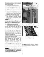
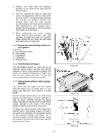
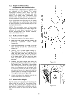
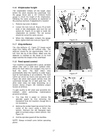
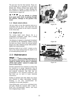
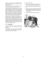
9.7 Inspect work table parallel to cutterhead The work table is set parallel to the cutterhead at the factory and no further adjustment should be necessary. If your machine is planing a taper, first check to see if the knives are set properly in the cutterhead. Then check to see if the work table is set parallel to the cutterhead. Proceed as follows: 1. Disconnect machine from power source. 2. Place the gauge block (Figure 18) on the work table directly under the edge of a knife as shown. Make slight contact by gently raising table. 3. Move the gauge block to the opposite end of the work table. NOTE: Distance from the work table to edge of knife should be the same at both ends. 9.8 Adjusting work table parallel to cutterhead (fine adjustment) If the gap difference determined in the previous section is greater than 0.004" and less than 0.016", perform the adjustment procedure as follows: 1. Determine which side of the table must be raised to correct the gap. 2. Locate the two socket head cap screws in the table casting for each of the columns (Figure 19). Loosen both sets of screws for each column on the side you wish to adjust. 3. Push down or pull up the cutterhead assembly in the desired direction. Hold the assembly in position and retighten the cap screws. 4. Re-check the table-to-cutterhead parallelism again as described in the previous section, then repeat steps 1 through 3 until the deviation is less than 0.004". 9.9 Adjusting work table parallel to cutterhead (major adjustment) If the work table is not parallel to the cutterhead, perform the adjustment procedure as follows: 1. Disconnect machine from power source. 2. Remove bolts holding the planer to the stand. Carefully tilt planer on its side to expose underside of base (Figure 20). 3. Remove bolt (A, Figure 20) and loosen bolt (B, Figure 20) which will allow you to move the idler sprocket assembly (C, Figure 20) far enough to release tension on the chain. 14 Figure 18 Figure 19 Figure 20
-
 1
1 -
2
-
3
-
4
-
5
-
6
-
7
-
8
-
 9
9 -
 10
10 -
 11
11 -
 12
12 -
 13
13 -
 14
14 -
 15
15 -
 16
16 -
 17
17 -
 18
18 -
 19
19 -
20
-
21
-
22
-
23
-
24
-
25
-
26
-
27
-
28
-
29
-
30
-
31
-
32
-
33
-
34
-
35
-
36
 |
 |
