JET Tools JWP-15HH User Manual - Page 16
Height of infeed roller, chipbreaker and outfeed roller, Outfeed roller height, Infeed roller height
 |
View all JET Tools JWP-15HH manuals
Add to My Manuals
Save this manual to your list of manuals |
Page 16 highlights
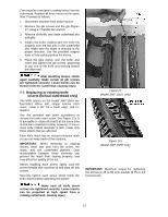
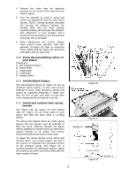
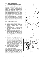
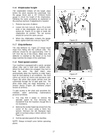
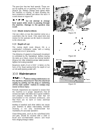
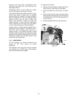
9.13 Height of infeed roller, chipbreaker and outfeed roller The infeed roller, chipbreaker and outfeed roller are adjusted at the factory. The height relationship between these items and the cutterhead is crucial for accurate and safe planing. The infeed roller, chipbreaker, and outfeed roller should each be set at 0.02" (0.5mm) below the cutting circle. See Figure 24. If any adjustments are necessary for the infeed roller, chipbreaker, or outfeed roller, they should be done carefully. Use the following steps as an example of procedure. NOTE: This procedure uses a home-made gauge block and feeler gauges, which should be sufficient for most planer operations. If very precise measurements are desired, however, use a dial indicator device. 9.14 Outfeed roller height 1. Disconnect machine from power source. 2. Make sure the knives are set properly as previously explained under "Knife Adjustment." 3. Place the gauge block (F, Figure 25) on the table directly beneath the cutterhead (D, Figure 25). 4. Using a 0.02" (0.5mm) feeler gauge (G, Figure 25) placed on top of the gauge block, raise the work table until the knife just touches the feeler gauge when the knife is at its lowest point. Do not move the work table any farther until the outfeed roller is adjusted. 5. Remove the feeler gauge and move the gauge block (F, Figure 25) under one end of the outfeed roller. The bottom of the outfeed roller should just touch the top of the gauge block. If an adjustment to the outfeed roller is necessary, loosen the lock nut (J, Figure 26) and turn screw (H, Figure 26) until the outfeed roller just touches the gauge block. Then tighten lock nut (J, Figure 26). 6. Check and adjust the opposite end of the outfeed roller in the same manner. 9.15 Infeed roller height Use the exact same procedure for checking the infeed roller as you did for the outfeed roller, Use the .02" (0.5mm) feeler gauge atop the gauge block. If adjustment is necessary, use the lock nut and screw on each end of the infeed roller. 16 Figure 24 Figure 25
-
 1
1 -
2
-
3
-
4
-
5
-
6
-
7
-
8
-
9
-
10
-
 11
11 -
 12
12 -
 13
13 -
 14
14 -
 15
15 -
 16
16 -
 17
17 -
 18
18 -
 19
19 -
 20
20 -
 21
21 -
22
-
23
-
24
-
25
-
26
-
27
-
28
-
29
-
30
-
31
-
32
-
33
-
34
-
35
-
36
 |
 |
