JET Tools JWP-15HH User Manual - Page 15
Know the transmitting rollers of, your planer, Anti-kickback fingers, Infeed and outfeed roller
 |
View all JET Tools JWP-15HH manuals
Add to My Manuals
Save this manual to your list of manuals |
Page 15 highlights
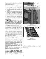
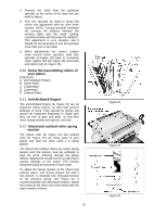
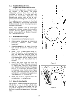
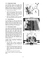
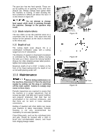
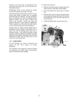
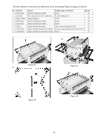
4. Remove the chain from the particular sprocket on the corner of the base that you need to adjust. 5. Turn the sprocket by hand to bring that corner into adjustment with the other three corners. NOTE: Turning sprocket clockwise will increase the distance between the working table and the head casting; counterclockwise will decrease the distance. This adjustment is very sensitive and it should not be necessary to turn the sprocket more than one or two teeth. 6. When adjustments are correct, replace chain around corner sprocket, slide idler sprocket (C-Figure 20) back to re-tension chain, tighten bolt (B, Figure 20) and insert and tighten bolt (A, Figure 20). 9.10 Know the transmitting rollers of your planer (Figure 21) A. Anti-Kickback Fingers B. Infeed Roller C. Chipbreaker D. Cutterhead E. Outfeed Roller 9.11 Anti-kickback fingers The anti-kickback fingers (A, Figure 21) are an important safety feature, as they help prevent kickback of stock. They operate by gravity and should be inspected frequently to make sure they are free of gum and pitch, so that they move independently and operate correctly. 9.12 Infeed and outfeed roller spring tension The infeed roller (B, Figure 21) and outfeed roller (E, Figure 21) are those parts of your planer that feed the stock while it is being planed. The infeed and outfeed rollers are under spring tension and this tension must be sufficient to feed the stock uniformly through the planer without slipping but should not be so tight that it causes damage to the board. The tension should be equal at both ends of each roller. To adjust the spring tension of the infeed and outfeed rollers, turn screws (Figure 22) with a hex wrench. A clockwise turn increases tension on the pressure spring. See Figure 23. A counterclockwise turn decreases tension. Adjust the screws at the other end of the rollers with the same number of turns. 15 Figure 21 Figure 22 Figure 23
-
 1
1 -
2
-
3
-
4
-
5
-
6
-
7
-
8
-
9
-
 10
10 -
 11
11 -
 12
12 -
 13
13 -
 14
14 -
 15
15 -
 16
16 -
 17
17 -
 18
18 -
 19
19 -
 20
20 -
21
-
22
-
23
-
24
-
25
-
26
-
27
-
28
-
29
-
30
-
31
-
32
-
33
-
34
-
35
-
36
 |
 |
