JET Tools JWP-15HH User Manual - Page 17
Chipbreaker height, Chip deflector, Feed speed control
 |
View all JET Tools JWP-15HH manuals
Add to My Manuals
Save this manual to your list of manuals |
Page 17 highlights
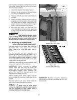
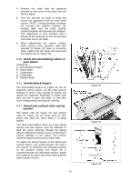
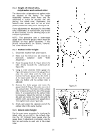
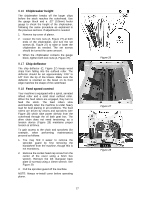
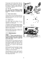
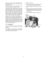
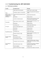
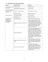
9.16 Chipbreaker height The chipbreaker breaks off the larger chips before the stock reaches the cutterhead. Use the gauge block and a .02" (0.5mm) feeler gauge to check the height of the chipbreaker, following the same procedure as explained in the previous sections. If adjustment is needed: 1. Remove top cover of planer. 2. Loosen the lock nuts (A, Figure 27) at both ends of the chipbreaker, and turn the set screws (B, Figure 27) to raise or lower the chipbreaker as needed. The set screws should be turned the same amount. 3. When the chipbreaker contacts the gauge block, tighten both lock nuts (A, Figure 27). 9.17 Chip deflector The chip deflector (C, Figure 27) keeps wood chips from falling into the outfeed roller. The deflector should be set approximately 1/16" to 1/8" from the tip of the knives. Make sure the deflector is oriented so the bevel on its front edge matches the shape of the cutterhead. 9.18 Feed speed control Your machine is equipped with a spiral, serrated infeed roller and a solid steel outfeed roller. When the feed rollers are engaged, they turn to feed the stock. The feed rollers slow automatically when the machine is under heavy load for best planing in all conditions. The feed rollers are driven by chains and sprockets (see Figure 28) which take power directly from the cutterhead through the oil bath gear box. The drive chain does not need tensioning, as a tension device (Figure 28) maintains proper tension at all times. To gain access to the chain and sprockets (for example, when performing maintenance) proceed as follows: 1. You may find it easier to remove the sprocket guard by first removing the handwheel from the machine, though this is not mandatory. 2. Remove the socket head cap screw from the center of the cover using a 6mm hex wrench. Remove the left triangular back plate (2 screws) using a 10mm wrench. See Figure 29. 3. Pull the sprocket guard off the machine. NOTE: Always re-install cover before operating planer. 17 Figure 26 Figure 27 Figure 28
-
 1
1 -
2
-
3
-
4
-
5
-
6
-
7
-
8
-
9
-
10
-
11
-
 12
12 -
 13
13 -
 14
14 -
 15
15 -
 16
16 -
 17
17 -
 18
18 -
 19
19 -
 20
20 -
 21
21 -
 22
22 -
23
-
24
-
25
-
26
-
27
-
28
-
29
-
30
-
31
-
32
-
33
-
34
-
35
-
36
 |
 |
