JVC GD-V4200PZW GD-V4200PZW plasma display 32 page instruction manual (English - Page 10
Connections - resolution
 |
View all JVC GD-V4200PZW manuals
Add to My Manuals
Save this manual to your list of manuals |
Page 10 highlights
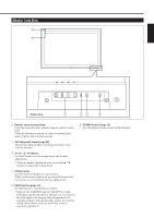
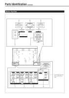
Connections Precautions • Before making connections, turn off all the equipment. • Plugs should be firmly inserted; poor connection could cause noise. • To unplug a cord, be sure to grasp its plug and pull it out. • Connect the power cord after having finished all other connections. • Refer also to the user manual of each piece of equipment. Available Signals Video signals The following signals can be input to this Monitor: • VIDEO A and VIDEO B terminals accept - PAL, NTSC, and SECAM signals. • COMPONENT terminals accept - 480i, 576i, 480p, 720p, and 1080i signals. (For GD-V4200PCE and GD-V4200PCE-G, to input the above signals, you need to install the video interface kit (IF-C420P1W), which is separately purchased.) Computer signals (Preset and user-defined video modes) This Monitor has 13 preset video mode for the most popular industrial standard (marked with ¶ in the table below), and the signals of the following image resolutions can be input to the RGB input terminals. For less common video modes, this Monitor can also display a picture, and memorize the video modes as user-defined video modes (up to five modes). When a signal other than any of the preset modes is input, it will automatically be stored as a user-defined video mode, and when a sixth user-defined video signal is input, the first mode will be erased from memory. No. Signal name 1 PC98 2 VGA400-70 3 VGA480-60 4 VGA480-72 5 VGA480-75 6 MAC13" 7 SVGA-56 8 SVGA-60 9 SVGA-72 10 XGA-60 11 XGA-70 12 RGB15K-60 13 RGB15K-50 - User-defined - User-defined Screen resolution Horizontal Vertical 640 400 640 400 640 480 640 480 640 480 640 480 800 600 800 600 800 600 1024 768 1024 768 - - - - - - - - Horizontal Vertical Frequency (kHz) Frequency (Hz) 24.8 56.4 31.5 70.1 31.5 59.9 37.9 72.8 37.5 75.0 35.0 66.7 35.2 56.3 37.9 60.3 48.1 72.2 48.4 60.0 56.5 70.1 15.7 59.9 15.6 50.0 15.0 - 16.0 50.0 - 75.0 16.0 - 56.0 50.0 - 75.0 Scan system Non-interlace Non-interlace Non-interlace Non-interlace Non-interlace Non-interlace Non-interlace Non-interlace Non-interlace Non-interlace Non-interlace Interlace Interlace Interlace Non-interlace Preset setting Notes: • When you are viewing XGA, setting the refresh rate (vertical scan frequency) of your personal computer to 60 Hz will enhance the video image. • When a signal other than listed above is input, a part of the screen may become void or an unnecessary picture may appear. • Signals, though they are within the acceptable range of frequencies, may not be displayed normally, depending on the signal type. • Depending on the connected equipment, the Monitor may not be compatible with composite sync (Cs) or G on sync signals. • When a preset mode signal is input, the vertical frequency displayed on the screen will have an "*" shown at its right top position. • When No. 7 to No. 11 signals are input, thin lines may happen to be hard to view on the screen, due to the internal digital processing. 10
-
 1
1 -
2
-
3
-
4
-
 5
5 -
 6
6 -
 7
7 -
 8
8 -
 9
9 -
 10
10 -
 11
11 -
 12
12 -
 13
13 -
 14
14 -
 15
15 -
16
-
17
-
18
-
19
-
20
-
21
-
22
-
23
-
24
-
25
-
26
-
27
-
28
-
29
-
30
-
31
-
32
 |
 |
