JVC GD-V4200PZW GD-V4200PZW plasma display 32 page instruction manual (English - Page 11
Connection Examples
 |
View all JVC GD-V4200PZW manuals
Add to My Manuals
Save this manual to your list of manuals |
Page 11 highlights
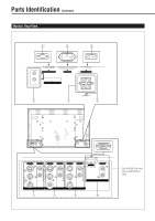
ENGLISH Connection Examples VCR To audio output terminals Personal computer (used as the playback source) To video output terminal To S-video output terminal To monitor output terminal To audio output terminals Hi-vision equipment/ DVD, etc. VIDEO AUDIO VIDEO AUDIO Y/C Y/C IN IN R R L/MONO OUT L/MONO OUT VIDEO A VIDEO B To audio output terminals To video output terminals Personal computer (used to control the Monitor) To RS-232C terminal VIDEO AUDIO Y PB / B-Y R L/MONO PR / R-Y COMPONENT AUDIO PC L/MONO R RGB These terminals are not available for GD-V4200PCE and GD-V4200PCE-G. To use them, you need to install video interface kit (IF-C420P1W), which is separately purchased. Connecting a VCR • A VCR can also be connected to the VIDEO B terminal. • When both the video and S-video terminals are connected, the S-video terminal will have priority. • The video output terminal of the VIDEO B terminal can be used as the video input terminal. Power cord ( supplied) To a wall outlet External Speakers MENU/EXIT RM-C575 REMOTE CONTROL UNIT Remote control ID MODE ID SET MULTIPLE MONITOR ADJUSTMENT VOLUME MUTING VIDEO A VIDEO B COMPO. RGB POWER DISPLAY ASPECT Remote control cable (supplied) RS232C CONTROL IN AC INPUT (100V) OUT WIRED (MULTIPLE MONITOR ADJUSTMENT) REMOTE CONTROL I MAIN POWER SPEAKER OUT R L INTERNAL EXTERNAL To speaker input terminals When using external speakers, set this to EXTERNAL. 11
-
 1
1 -
2
-
3
-
4
-
5
-
 6
6 -
 7
7 -
 8
8 -
 9
9 -
 10
10 -
 11
11 -
 12
12 -
 13
13 -
 14
14 -
 15
15 -
 16
16 -
17
-
18
-
19
-
20
-
21
-
22
-
23
-
24
-
25
-
26
-
27
-
28
-
29
-
30
-
31
-
32
 |
 |
