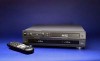
JVC SR-VS10U SR-VS10U dual transport MiniDV/S-VHS VTR 80 page instruction manu - Page 7
NOTES, S-VIDEO Connection, Component Video Connection - s vhs
 |
View all JVC SR-VS10U manuals
Add to My Manuals
Save this manual to your list of manuals |
Page 7 highlights
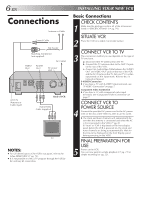
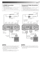
S-VIDEO Connection CONNECT VCR TO TV a- Connect the AV cables to the TV as explained in step 3 of "Basic Connections" (੬ pg. 6). b- Connect the S-Video cable between the S-VIDEO OUT jack on the rear of the VCR and the S-VIDEO IN jack on the TV. Antenna or Cable Coaxial Cable Flat Feeder Matching Transformer (not supplied) AC Outlet S-VIDEO VIDEO AUDIO OUT OUT OUT AC power inlet EN 7 Component Video Connection CONNECT VCR TO TV a- Connect the AV cables to the TV as explained in step 3 of "Basic Connections" (੬ pg. 6). b- Connect the component video cables between the DV PLAYBACK COMPONENT VIDEO OUT jacks on the rear of the VCR and the component video input jacks on the TV. Antenna or Cable Coaxial Cable Flat Feeder Matching Transformer (not supplied) DV PLAYBACK COMPONENT VIDEO OUT VIDEO OUT AUDIO OUT AC Outlet AC power inlet ANT. IN Y Pb Pr DV PLAYBACK COMPONENT VIDEO OUT S VIDEO IN 1 2 S VIDEO OUT CABLE BOX IN R L OUT1 R L OUT2 VIDEO AUDIO AC IN ANT. IN (Antenna or Cable input) S-Video Cable (supplied) Back of VCR Audio/Video Cable (supplied) S VIDEO IN ANT. IN Y Pb Pr DV PLAYBACK COMPONENT VIDEO OUT S VIDEO IN 1 2 S VIDEO OUT CABLE BOX IN R L OUT1 R L OUT2 VIDEO AUDIO AC IN ANT. IN (Antenna or Cable input) Back of VCR Audio/Video Cable (supplied) Component video Cable (not supplied) TV TV NOTES: ● To make the most of the Super VHS picture performance we recommend that you use the supplied S-VIDEO cable to connect your VCR to a TV with an S-VIDEO input connector. ● To operate the VCR with your TV using the S-VIDEO connection, set your TV to the AV mode using the TV's remote control. You can also use the TV/VCR button on the VCR's remote control to set your TV to the AV mode. (੬ pg. 66) NOTES: ● The menu screens of the VCR are not displayed on the TV. ● To change the settings or set the timer program on the menu screen, switch the TV's input mode for the connection with Audio/Video cables.
-
 1
1 -
 2
2 -
 3
3 -
 4
4 -
 5
5 -
 6
6 -
 7
7 -
 8
8 -
 9
9 -
 10
10 -
 11
11 -
 12
12 -
13
-
14
-
15
-
16
-
17
-
18
-
19
-
20
-
21
-
22
-
23
-
24
-
25
-
26
-
27
-
28
-
29
-
30
-
31
-
32
-
33
-
34
-
35
-
36
-
37
-
38
-
39
-
40
-
41
-
42
-
43
-
44
-
45
-
46
-
47
-
48
-
49
-
50
-
51
-
52
-
53
-
54
-
55
-
56
-
57
-
58
-
59
-
60
-
61
-
62
-
63
-
64
-
65
-
66
-
67
-
68
-
69
-
70
-
71
-
72
-
73
-
74
-
75
-
76
-
77
-
78
-
79
-
80
 |
 |
