Jenn-Air JGS9900CDS Installation Instruction - Page 11
Rear Wall Venting, Floor Venting
 |
View all Jenn-Air JGS9900CDS manuals
Add to My Manuals
Save this manual to your list of manuals |
Page 11 highlights
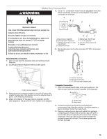
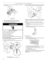
Rear Wall Venting 1. Mark the wall at the center of the cabinet opening. 5. Mount blower motor to the floor with 4 - #8 x ¾" hex head screws provided. Top View 2. Check for obstructions before marking the vent hole location. Mark a horizontal line 8 20.8 cm) from the floor. Mark a vertical line up to a maximum of 2¼" (7.9 cm) from the right side of the cabinet centerline. A 6. Go to the "Make Gas Connection" section. Floor Venting 1. Mark the floor at the center of the cabinet opening. B A. Maximum 2¼" (7.9 cm) from the right of center B. 8 20.8 cm) from floor 3. Draw and cut a 6¼" (15.8 cm) diameter hole. A A. 6¼" (15.8 cm) 4. Position blower motor in cabinet opening. Connect vent system to blower motor outlet using a vent clamp. Top View E C D A B A. 18¾" (47.6 cm) maximum from back wall forward into cabinet opening B. Inlet C. Vent system D. Vent clamp E. Wall vent 2. Position template on floor by matching the centerline of the template to the centerline drawn on the floor and place template 2¼" (5.7 cm) from the back wall. 3. Determine the correct position for the vent hole, depending on obstructions (joists) in the floor. The hole can be cut anywhere within the boundaries of either hatched area. Option 1: If using the back hatched area (bigger one), the blower inlet must face the left side as shown on the template. Option 2: If using the front hatched area (smaller one), the blower inlet must face the back. Top View Option 1 Option 2 B A A B A. Inlet from range B. Exhaust outlet 11
-
 1
1 -
2
-
3
-
4
-
5
-
 6
6 -
 7
7 -
 8
8 -
 9
9 -
 10
10 -
 11
11 -
 12
12 -
 13
13 -
 14
14 -
 15
15 -
 16
16 -
17
-
18
-
19
-
20
-
21
-
22
-
23
-
24
-
25
-
26
-
27
-
28
-
29
-
30
-
31
-
32
-
33
-
34
-
35
-
36
-
37
-
38
-
39
-
40
-
41
-
42
-
43
-
44
-
45
-
46
-
47
-
48
-
49
-
50
-
51
-
52
-
53
-
54
-
55
-
56
 |
 |
