Jenn-Air JGS9900CDS Installation Instruction - Page 12
Top View, View from Motor Side of Blower
 |
View all Jenn-Air JGS9900CDS manuals
Add to My Manuals
Save this manual to your list of manuals |
Page 12 highlights
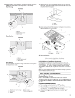
NOTE: If the template is misplaced, the following measurements can be used to determine the vent hole location. Top View B C D AE I H F G 6. Lift and rotate the motor 90° to reposition the electrical connection. A A. Electrical connector 7. Rotate bracket 90° and secure with 4 locknuts. A. 9" (22.8 cm) B. 3¹⁄₈" (7.9 cm) C. 8³⁄₈" (21.3 cm) D. 6³⁄₈" (16.2 cm) E. 2¼" (5.7 cm) F. 12½" (31.7 cm) G. 18¾" (47.6 cm) H. 1½" (3.8 cm) I. 3½" (8.9 cm) 4. Draw and cut a 6¼" (15.8 cm) diameter hole. 8. Remove the bracket from the other side of the blower motor, rotate 90° and secure with 4 locknuts. AB A. Option 1 B. Option 2 5. Remove the 4 locknuts on the blower side of the motor and remove the bracket. View from Motor Side of Blower A A. Electrical connector 12
-
 1
1 -
2
-
3
-
4
-
5
-
6
-
 7
7 -
 8
8 -
 9
9 -
 10
10 -
 11
11 -
 12
12 -
 13
13 -
 14
14 -
 15
15 -
 16
16 -
 17
17 -
18
-
19
-
20
-
21
-
22
-
23
-
24
-
25
-
26
-
27
-
28
-
29
-
30
-
31
-
32
-
33
-
34
-
35
-
36
-
37
-
38
-
39
-
40
-
41
-
42
-
43
-
44
-
45
-
46
-
47
-
48
-
49
-
50
-
51
-
52
-
53
-
54
-
55
-
56
 |
 |
