Jensen BT1611I Owners Manual - Page 6
Wiring - accessories
 |
UPC - 043258304155
View all Jensen BT1611I manuals
Add to My Manuals
Save this manual to your list of manuals |
Page 6 highlights
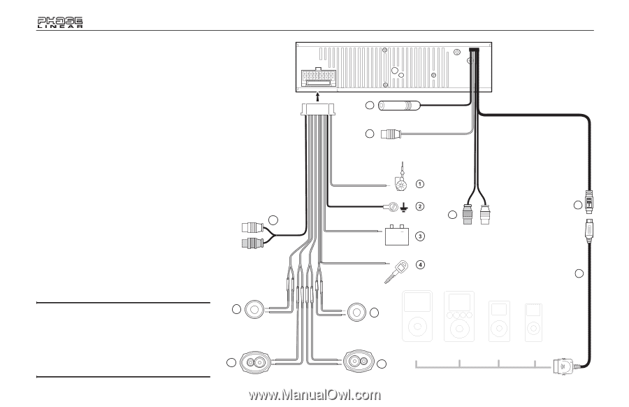
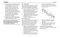
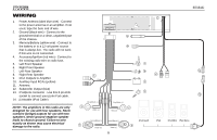
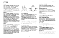
WIRING 1. Power Antenna (dark blue wire) - Connect to the power antenna or an amplifier. If not used, tape the bare end of wire. 2. Ground (black wire) - Connect to the ground terminal or a clean, unpainted part of the chassis. 3. Memory/Battery (yellow wire) - Connect to the battery or to a 12 volt power source that is always live. The radio will not work if this wire is not connected. 4. Accessory/Ignition (red wire) - Connect to the existing radio wire or radio fuse. 5. Left Front Speaker 6. Right Front Speaker 7. Left Rear Speaker 8. Right Rear Speaker 9. RCA Outputs to Amplifier 10. Auxiliary Input RCAs (yellow) 11. Antenna 12. Subwoofer Output (blue) 13. iPod/jLink connector - Use this 8-pin DIN socket to connect your jLink iPod cable. 14. jLinkcable (iPod Cable) NOTE: The amplifiers in this radio are only designed for use with four speakers. Never combine (bridge) outputs for use with two speakers. Never ground negative speaker leads to chassis ground. Failure to wire exactly as shown may cause electrical damage to the radio. 15A 11 12 BT1611i 13 10 9 Gray + 14 White/Black (-) 5 White (+) Gray/Black (-) 6 Gray (+) Green/Black (-) Violet/Black (-) 7 Green (+) Violet (+) 6 iPod Gen5 8 iPod iPod Mini iPod Nano
-
 1
1 -
 2
2 -
 3
3 -
 4
4 -
 5
5 -
 6
6 -
 7
7 -
 8
8 -
 9
9 -
 10
10 -
 11
11 -
 12
12 -
13
-
14
-
15
-
16
-
17
-
18
-
19
-
20
-
21
-
22
-
23
-
24
-
25
-
26
-
27
-
28
-
29
-
30
-
31
-
32
 |
 |