Konica Minolta A00F011 Service Manual
Konica Minolta A00F011 Manual
 |
View all Konica Minolta A00F011 manuals
Add to My Manuals
Save this manual to your list of manuals |
Konica Minolta A00F011 manual content summary:
- Konica Minolta A00F011 | Service Manual - Page 1
SERVICE MANUAL THEORY OF OPERATION magicolor 4650EN magicolor 4650DN 2007.11 Ver. 1.0 - Konica Minolta A00F011 | Service Manual - Page 2
S-2 WARNING INDICATIONS ON THE MACHINE S-18 MEASURES TO TAKE IN CASE OF AN ACCIDENT S-21 Composition of the service manual C-1 Notation of the service manual C-2 magicolor 4650EN/4650DN main body Outline ...1 Composition/Operation 9 Lower feeder unit Outline ...1 Composition/Operation 3 i - Konica Minolta A00F011 | Service Manual - Page 3
Blank Page ii - Konica Minolta A00F011 | Service Manual - Page 4
the product, KONICA MINOLTA BUSINESS TECHNOLOGIES, INC. (hereafter called the KMBT) strongly recommends that all servicing be performed only by KMBT-trained service technicians. Changes may have been made to this product to improve its performance after this Service Manual was printed. Accordingly - Konica Minolta A00F011 | Service Manual - Page 5
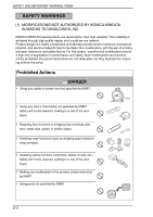
KONICA MINOLTA BUSINESS TECHNOLOGIES, INC. KONICA MINOLTA brand products are renowned for their high reliability. This reliability is achieved through high-quality design and a solid service . • Making any modification to the product unless instructed by KMBT • Using parts not specified by KMBT S-2 - Konica Minolta A00F011 | Service Manual - Page 6
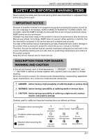
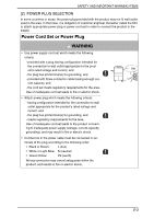
SAFETY AND IMPORTANT WARNING ITEMS [2] POWER PLUG SELECTION In some countries or areas, the power plug provided with the product may not fit wall outlet used in the area. In that case, it is obligation of customer engineer (hereafter called the CE) to attach appropriate power plug or power cord set - Konica Minolta A00F011 | Service Manual - Page 7
ITEMS [3] CHECKPOINTS WHEN PERFORMING ON-SITE SERVICE KONICA MINOLTA brand products are extensively tested before shipping, • Make sure the power cord is plugged in the wall outlet securely. Contact problems may lead to increased resistance, overheating, and the risk of fire. • Check whether - Konica Minolta A00F011 | Service Manual - Page 8
measure is provided, secure the cord with the fixture properly. If the power cord (inlet type) is not connected to the product securely, a contact problem may lead to increased resistance, overheating, and risk of fire. • Check whether the power cord is not stepped on or pinched by a table and - Konica Minolta A00F011 | Service Manual - Page 9
SAFETY AND IMPORTANT WARNING ITEMS Wiring WARNING • Never use multi-plug adapters to plug multiple power cords in the same outlet. If used, the risk of fire exists. • When an extension cord is required, use a specified one. Current that can flow in the extension cord is limited, so using a too long - Konica Minolta A00F011 | Service Manual - Page 10
an earthquake and so on, the product may slide, leading to a injury. Inspection before Servicing CAUTION • Before conducting an inspection, read all relevant documentation (service manual, technical notices, etc.) and proceed with the inspection following the prescribed procedure in safety clothes - Konica Minolta A00F011 | Service Manual - Page 11
belt, leading to a risk of injury. • Take every care when servicing with the external cover detached. High-voltage exists around the drum unit. leading to a risk of electric shock or fire. • Carefully remove all toner remnants and dust from electrical parts and electrode units such as a charging - Konica Minolta A00F011 | Service Manual - Page 12
and sign of leakage. Current can leak, leading to a risk of trouble or fire. • Before disassembling or adjusting the write unit (P/H unit) battery, replace it with a new lithium battery specified in the Parts Guide Manual. Dispose of the used lithium battery using the method specified by local - Konica Minolta A00F011 | Service Manual - Page 13
, etc.) A risk of product trouble, electric shock, and fire exists. Handling of Consumables WARNING • Toner and developer are not harmful substances, Never throw the used cartridge and toner into fire. You may be burned due to dust explosion. Handling of Service Materials CAUTION • Unplug the power - Konica Minolta A00F011 | Service Manual - Page 14
SAFETY AND IMPORTANT WARNING ITEMS Handling of Service Materials CAUTION • Use only a small amount of cleaner at a time and take care not to spill any liquid. If this happens, immediately wipe it off. A - Konica Minolta A00F011 | Service Manual - Page 15
du même type ou d'un type équivalent recommandé par le constructeur. Mettre au rebut les batteries usagées conformément aux instructions du fabricant. Denmark ADVARSEL! Lithiumbatteri - Eksplosionsfare ved fejlagtig håndtering. Udskiftning må kun ske med batteri af samme fabrikat og type. Levér det - Konica Minolta A00F011 | Service Manual - Page 16
certified as a Class 1 laser product. There is no possibility of danger from a laser, provided the machine is serviced according to the instruction in this manual. 5.1 Internal Laser Radiation semiconductor laser Maximum power of the laser diode Maximum average radiation power (*) Wavelength *at - Konica Minolta A00F011 | Service Manual - Page 17
Food and Drug Administration of the U.S. Department of Health and Human Services (DHHS). This means that the device does not produce hazardous laser or performance of procedures other than those specified in this manual may result in hazardous radiation exposure. semiconductor laser Maximum power - Konica Minolta A00F011 | Service Manual - Page 18
Finland, Sweden LUOKAN 1 LASERLAITE KLASS 1 LASER APPARAT SAFETY AND IMPORTANT WARNING ITEMS VAROITUS! • Laitteen käyttäminen muulla kuin tässä käyttöohjeessa mainitulla tavalla saat- taa altistaa käyttäjän turvallisuusluokan 1 ylittävälle näkymättömälle lasersäteilylle. puolijohdelaser - Konica Minolta A00F011 | Service Manual - Page 19
SAFETY AND IMPORTANT WARNING ITEMS 5.2 Laser Safety Label • A laser safety label is attached to the inside of the machine as shown below. A00FP0E500DA 5.3 Laser Caution Label • A laser caution label is attached to the outside of the machine as shown below. S-16 A00FP0E501DA - Konica Minolta A00F011 | Service Manual - Page 20
performed in the laser beam path, such as when working around the printerhead and PC Drum, be sure first to turn the printer OFF. • If the job requires that the printer be left ON, take off your watch and ring and wear laser protective goggles. • A highly reflective tool can be dangerous if - Konica Minolta A00F011 | Service Manual - Page 21
SAFETY AND IMPORTANT WARNING ITEMS WARNING INDICATIONS ON THE MACHINE Caution labels shown are attached in some areas on/in the machine. When accessing these areas for maintenance, repair, or adjustment, special care should be taken to avoid burns and electric shock. High voltage • This area - Konica Minolta A00F011 | Service Manual - Page 22
SAFETY AND IMPORTANT WARNING ITEMS High voltage • This area generates high voltage. Be careful not to touch here when the power is turned ON to avoid getting an electric shock. High voltage • This area generates high voltage. Be careful not to touch here when the power is turned ON to avoid getting - Konica Minolta A00F011 | Service Manual - Page 23
is dangerous. WARNING • Do not burn used Waste Toner Bottle. Toner expelled from the fire is dangerous. Y WARNING • Do not burn used Toner Cartridge. Toner expelled from the fire is dangerous. A00FP0C504DA CAUTION: • soiled and therefore the caution cannot be read, contact our Service Office. S-20 - Konica Minolta A00F011 | Service Manual - Page 24
must be notified. 3. To determine the cause of the accident, conditions and materials must be recorded through direct on-site checks, in accordance with instructions issued by KMBT. 4. For reports and measures concerning serious accidents, follow the regulations specified by every distributor. S-21 - Konica Minolta A00F011 | Service Manual - Page 25
MEASURES TO TAKE IN CASE OF AN ACCIDENT Blank Page S-22 - Konica Minolta A00F011 | Service Manual - Page 26
Composition of the service manual This service manual consists of Theory of Operation section and Field Service section to explain the main machine and system, and control system GENERAL: MAINTENANCE: ADJUSTMENT/SETTING: TROUBLESHOOTING: APPENDIX: Explanation of system - Konica Minolta A00F011 | Service Manual - Page 27
Notation of the service manual A. Product name In this manual, each of the products is described as follows: (1) magicolor 4650EN/4650DN Main body (2) Microsoft Windows 98: Windows 98 Microsoft Windows Me: Windows Me Microsoft Windows NT 4.0: Windows NT 4.0 or Windows NT Microsoft Windows - Konica Minolta A00F011 | Service Manual - Page 28
SERVICE MANUAL THEORY OF OPERATION magicolor 4650EN magicolor 4650DN Main Body 2007.11 Ver. 1.0 - Konica Minolta A00F011 | Service Manual - Page 29
may not coincide with the actual machine. When any change has been made to the descriptions in the service manual, a revised version will be issued with a revision mark added as required. Revision mark: • To indicate clearly a section revised, show 1 to the left of the revised - Konica Minolta A00F011 | Service Manual - Page 30
Ver. 1.0 Nov. 2007 CONTENTS magicolor 4650EN/4650DN main body Outline 1. System Toner replenishing mechanism 19 8.3.4 Toner level detection 20 8.3.5 Toner near-empty condition detection 20 8.3.6 Toner empty condition detection 21 8.3.7 Toner empty condition detection control 21 8.3.8 Toner - Konica Minolta A00F011 | Service Manual - Page 31
magicolor 4650EN magicolor 4650DN Outline Composition/Operation Theory of operation Ver. 1.0 Nov. 2007 9.2 control 30 12.2.2 Toner collecting port shutter mechanism 31 12.2.3 Toner flow 32 12.2.4 Developing system 33 12.2.5 Cleaning mechanism 34 12.2.6 Toner collecting port shutter mechanism - Konica Minolta A00F011 | Service Manual - Page 32
magicolor 4650EN magicolor 4650DN Outline Composition/Operation Theory of operation Ver. 1.0 Nov. 2007 14. Waste toner box-in-position detection mechanism 55 15.3.8 Waste toner flow in the waste toner box 55 15.3.9 Waste toner near-full condition detection control 56 15.3.10 Waste toner full - Konica Minolta A00F011 | Service Manual - Page 33
4650EN magicolor 4650DN Outline Composition/Operation Theory of operation Ver. 1.0 Nov. 2007 17.3.6 Tray open/close detection control 65 17.3.7 Media misfeed detection control 65 18. Conveyance section (IDC sensor 66 18.1 Composition ...66 18.1.1 Drive ...67 18.2 Operation...67 18.2.1 Toner - Konica Minolta A00F011 | Service Manual - Page 34
magicolor 4650EN magicolor 4650DN Outline Composition/Operation Theory of operation Ver. 1.0 Nov. 2007 22.1 ...89 23.2 Drive ...90 23.3 Operation ...91 23.3.1 Outline...91 23.3.2 Switchback guide movable mechanism 92 23.3.3 Paper exit switching mechanism 93 23.3.4 Transport /Paper re-feed mechanism - Konica Minolta A00F011 | Service Manual - Page 35
Theory of operation Ver. 1.0 Nov. 2007 Blank Page vi Composition/Operation Outline magicolor 4650EN magicolor 4650DN - Konica Minolta A00F011 | Service Manual - Page 36
magicolor 4650EN magicolor 4650DN Outline Theory of operation Ver. 1.0 Nov. 2007 Outline 1. System configuration [5] [4] [3] 1. System configuration [1] [1] magicolor 4650EN/4650DN [2] Lower feeder unit [3] Memory (DIMM) [4] Hard disk kit [5] CF adapter [2] A011T1C501AA 1 - Konica Minolta A00F011 | Service Manual - Page 37
magicolor 4650EN magicolor 4650DN Outline 2. Product specifications Theory of operation Ver. 1.0 Nov. 2007 2. Product specifications A. Type Type Desktop tandem full-color A4 laser beam printer Printing system Electro photographic Printing System Exposure system 4 laser diode and 1 - Konica Minolta A00F011 | Service Manual - Page 38
magicolor 4650EN magicolor 4650DN Outline Theory of operation Ver. 1.0 Nov. 2007 2. Product specifications C. Media Media type Media dimensions Type Paper source (maximum tray capacity) Tray1 Tray2 Plain paper ( - Konica Minolta A00F011 | Service Manual - Page 39
magicolor 4650EN magicolor 4650DN Outline 2. Product Service Pack 4 or later) Mac OS X (10.2 or later; We recommend installing the newest patch), Mac OS X Server (10.2 or later) Red Hat Linux 9.0, SuSE Linux 8.2 Free hard disk space Approximately 20 MB of free hard disk space for printer driver - Konica Minolta A00F011 | Service Manual - Page 40
magicolor 4650EN magicolor 4650DN Outline Theory of operation Ver. 1.0 Nov. 2007 3. Section configuration 3. Section configuration Toner supply section Transfer belt section Fusing section Transfer section Duplex section Print unit section Media feed section (Tray 1) Write section Media - Konica Minolta A00F011 | Service Manual - Page 41
magicolor 4650EN magicolor 4650DN 4. Media path 4. Media path Theory of operation Ver. 1.0 Nov. 2007 A011T1C503AA Outline 6 - Konica Minolta A00F011 | Service Manual - Page 42
magicolor 4650EN magicolor 4650DN Outline Theory of operation Ver. 1.0 Nov. 2007 5. Image creation process 5. Image creation process [9] Transfer belt cleaning [6] 1st image transfer [8] Media separation [7] 2nd image transfer [2] PC drum [10] PC drum cleaning [5] Developing [1] Printer - Konica Minolta A00F011 | Service Manual - Page 43
5. Image creation process Theory of operation Ver. 1.0 Nov. 2007 magicolor 4650EN magicolor 4650DN Outline Blank Page 8 - Konica Minolta A00F011 | Service Manual - Page 44
Y Developing Y Developing Y TOD Y TOD M TOD C TOD K 1st transfer pressure/retraction 1st transfer rem 2nd transfer pressure/retraction 2nd transfer rem 6. Overall composition A011T2E548AA 9 Composition/Operation magicolor 4650EN magicolor 4650DN - Konica Minolta A00F011 | Service Manual - Page 45
magicolor 4650EN magicolor 4650DN 6. Overall composition 6.2 Control block diagram Theory of operation Ver.1.0 Nov. 2007 Operation board Print control board (PRCB) Image processing Leser drive board MFP board ( - Konica Minolta A00F011 | Service Manual - Page 46
magicolor 4650EN magicolor 4650DN Theory of operation Ver. 1.0 Nov. 2007 7. Write section 7.1 Composition 7. Write section A011T2C515AA G2 lens Return mirror/2nd 4138to2001c0 SOS lens Index board G1 lens - Konica Minolta A00F011 | Service Manual - Page 47
magicolor 4650EN magicolor 4650DN Composition/Operation 7. Write section Theory of operation Ver.1.0 Nov. 2007 7.2 Operation 7.2.1 Overview • Four semiconductor lasers provided, one for each of the four different colors. A - Konica Minolta A00F011 | Service Manual - Page 48
magicolor 4650EN magicolor 4650DN Theory of operation Ver. 1.0 Nov. 2007 7. Write section 7.2.3 Laser emission timing • When a ready signal is detected after the lapse of a given period of time - Konica Minolta A00F011 | Service Manual - Page 49
magicolor 4650EN magicolor 4650DN 7. Write section Theory of operation Ver.1.0 Nov. 2007 7.2.5 Laser light correction control • In a tandem engine that has an image forming process for each color of toner, incorrect color registration tends to occur due to variations in parts of the main body used - Konica Minolta A00F011 | Service Manual - Page 50
magicolor 4650EN magicolor 4650DN Theory of operation Ver. 1.0 Nov. 2007 8. Toner supply section 8.1 Composition 8. Toner supply section A011T2C516AA TC detection board (CSIC) A011T2C525AA Conveyance screw A011T2C006DA Toner collecting port Agitating blade Conveyance screw A011T2C007DA - Konica Minolta A00F011 | Service Manual - Page 51
magicolor 4650EN magicolor 4650DN 8. Toner supply section 8.2 Drive Theory of operation Ver.1.0 Nov. 2007 Front view Toner supply motor/C, K (M7) Toner supply motor/Y, M (M6) 3D view 4138to2599c0 Toner supply motor/C, K (M7) Toner supply motor/Y, M (M6) Agitating blade Conveyance screw - Konica Minolta A00F011 | Service Manual - Page 52
magicolor 4650EN magicolor 4650DN Theory of operation Ver. 1.0 Nov. 2007 8. Toner supply section 8.3 Operation 8.3.1 Toner conveying mechanism • The toner supply motor is turned either forward or backward to drive the agitating blade and the conveyance screw. • The agitating blade provided in the - Konica Minolta A00F011 | Service Manual - Page 53
magicolor 4650EN magicolor 4650DN 8. Toner supply section Theory of operation Ver.1.0 Nov. 2007 8.3.2 Toner collecting port shutter mechanism • The toner collecting port is equipped with a shutter mechanism that prevents toner from being spilled out when the toner cartridge is removed from the - Konica Minolta A00F011 | Service Manual - Page 54
magicolor 4650EN magicolor 4650DN Theory of operation Ver. 1.0 Nov. 2007 8. Toner supply section 8.3.3 Toner replenishing mechanism • The toner supply motor is energized according to the condition of the toner level sensor for each color of toner. Toner is then supplied from the toner cartridge - Konica Minolta A00F011 | Service Manual - Page 55
magicolor 4650EN magicolor 4650DN 8. Toner supply section Theory of operation Ver.1.0 Nov. 2007 8.3.4 Toner level detection • The toner level is determined by the accumulated time of rotation of the toner supply motor. • The toner level can be checked through MENU/PRINT MENU/STATISTICS PAGE. - Konica Minolta A00F011 | Service Manual - Page 56
magicolor 4650EN magicolor 4650DN Composition/Operation Theory of operation Ver. 1.0 Nov. 2007 8. Toner supply section 8.3.6 Toner empty condition detection A. Toner empty condition detection mechanism • The print unit has a toner empty condition detecting mechanism. Based on the amount of toner - Konica Minolta A00F011 | Service Manual - Page 57
4650EN magicolor 4650DN Composition/Operation PC motor A011T2C517AA PU detection board (CSIC) A011T2C526AA Developing motor Replenishing screw Agitating screw Supply roller Developing roller A011T2C013DA Photo conductor Cleaning blade Charge corona A011T2C014DA Toner collecting screw - Konica Minolta A00F011 | Service Manual - Page 58
magicolor 4650EN magicolor 4650DN Theory of operation Ver. 1.0 Nov. 2007 9. Print unit section ( unit life control • Each print unit is provided with a PU detection board that detects state of a toner cartridge placement, a new PU, a print unit life. • The main body attempts to perform a detection - Konica Minolta A00F011 | Service Manual - Page 59
magicolor 4650EN magicolor 4650DN 10. Print unit section (photo conductor) Theory of operation Ver.1.0 Nov. 2007 10. Print unit section (photo conductor) 10.1 Composition Photo conductor Composition/Operation - Konica Minolta A00F011 | Service Manual - Page 60
magicolor 4650EN magicolor 4650DN Theory of operation Ver. 1.0 Nov. 2007 10. Print unit section ( to suppress incorrect color registration and uneven pitch. • To stop the drive for the color toner cartridges in the monochrome mode, different motors are used to drive the color photo conductors and - Konica Minolta A00F011 | Service Manual - Page 61
magicolor 4650EN magicolor 4650DN 10. Print unit section (photo conductor) Theory of operation Ver.1.0 Nov. of the photo conductors, causing white bands to occur in the image. • To prevent this image problem, the photo conductor is turned so as to allow its surface facing the charge corona unit to - Konica Minolta A00F011 | Service Manual - Page 62
magicolor 4650EN magicolor 4650DN Theory of operation Ver. 1.0 Nov. 2007 11. Print unit section (charge corona) 11. Print unit section (charge corona) 11.1 Composition A011T2C517AA A011T2C526AA Charge corona - Konica Minolta A00F011 | Service Manual - Page 63
magicolor 4650EN magicolor 4650DN Composition/Operation 11. Print unit section (charge corona) Theory of operation Ver.1.0 Nov. 2007 11.2 Operation 11.2.1 Charge corona unit ON/OFF control Polygon - Konica Minolta A00F011 | Service Manual - Page 64
12. Print unit section (developing) magicolor 4650EN magicolor 4650DN Composition/Operation A011T2C517AA A011T2C526AA Replenishing screw Agitating screw Supply roller Photo conductor Cleaning blade Charge corona Developing roller Toner collecting screw A011T2C014DA Color developing motor - Konica Minolta A00F011 | Service Manual - Page 65
magicolor 4650EN magicolor 4650DN 12. Print unit section (developing) 12.2 Operation 12.2.1 Developing drive control Polygon motor Transport motor (M3) Color PC drum motor (M2) Color PC drum - Konica Minolta A00F011 | Service Manual - Page 66
magicolor 4650EN magicolor 4650DN Theory of operation Ver. 1.0 Nov. 2007 12. Print unit section (developing) 12.2.2 Toner collecting port shutter mechanism • The toner collecting port is equipped with a shutter mechanism that prevents toner from being spilled out when the print unit is removed - Konica Minolta A00F011 | Service Manual - Page 67
magicolor 4650EN magicolor 4650DN 12. Print unit section (developing) Theory of operation Ver.1.0 Nov. 2007 12.2.3 Toner flow 1. Toner stored in the toner cartridge is agitated by the agitating blade and conveyed onto the front side of the toner cartridge by the conveyance screw. 2. Toner - Konica Minolta A00F011 | Service Manual - Page 68
magicolor 4650EN magicolor 4650DN Composition/Operation Theory of operation Ver. 1.0 Nov. 2007 12. other than the development, only the DC component of the developing bias voltage is applied. 5. Toner sticks to the photo conductor when the AC component of the developing bias voltage (Vpp) is - Konica Minolta A00F011 | Service Manual - Page 69
magicolor 4650EN magicolor 4650DN Composition/Operation 12. Print unit section (developing) Theory of operation Ver.1.0 Nov. 2007 12.2.5 Cleaning mechanism A. Cleaning operation 1. The cleaning blade is pressed against the surface of the photo conductor to remove toner left off the surface ( - Konica Minolta A00F011 | Service Manual - Page 70
13.1 Composition 13. Transfer section (1st transfer) magicolor 4650EN magicolor 4650DN Composition/Operation A011T2C518AA 1st image transfer retraction position roller/M Pressure cam roller/K Cleaning blade 4138to2035c2 Toner collecting screw 1st image transfer pressure/retraction clutch - Konica Minolta A00F011 | Service Manual - Page 71
magicolor 4650EN magicolor 4650DN 13. Transfer section (1st transfer) 13.2 Drive Theory of operation Ver.1.0 Nov. 2007 1st image motion 4138to2041c1 Sliding plate Pressure cam 1st transfer roller/Y, /M, /C, /K Sliding plate Composition/Operation Toner collecting screw 36 A011T2C033DA - Konica Minolta A00F011 | Service Manual - Page 72
magicolor 4650EN magicolor 4650DN Theory of operation Ver. 1.0 Nov. 2007 13. Transfer section (1st transfer) 13.3 Operation 13.3.1 1st transfer output control • To transfer the toner transfer roller pressure/retraction control • To extend the service life of the photo conductor/Y, M, C, the - Konica Minolta A00F011 | Service Manual - Page 73
magicolor 4650EN magicolor 4650DN 13. Transfer section (1st transfer) Theory of operation Ver.1.0 Nov. 2007 13.3.3 1st transfer roller pressure operation 1. Rotation of the Transport motor is transmitted - Konica Minolta A00F011 | Service Manual - Page 74
magicolor 4650EN magicolor 4650DN Theory of operation Ver. 1.0 Nov. 2007 13. Transfer section (1st transfer) 13.3.4 1st transfer roller retraction operation 1. Rotation of the Transport motor is transmitted - Konica Minolta A00F011 | Service Manual - Page 75
magicolor 4650EN magicolor 4650DN 13. Transfer section (1st transfer) Theory of operation Ver.1.0 Nov. 2007 13.3.5 1st transfer roller pressure/retraction position control A. Pressure position control • The pressure - Konica Minolta A00F011 | Service Manual - Page 76
magicolor 4650EN magicolor 4650DN Theory of operation Ver. 1.0 Nov. 2007 13. Transfer section (1st transfer) 13.3.6 Transfer belt cleaning mechanism • To scrape residual toner off the surface of the transfer belt, the transfer belt is provided with a cleaning blade. • The cleaning blade is in - Konica Minolta A00F011 | Service Manual - Page 77
magicolor 4650EN magicolor 4650DN 13. Transfer section (1st transfer) Theory of operation Ver.1.0 Nov. 2007 13.3.7 1st transfer belt cleaning control • If there is a possibility of the main body being stopped with toner left on the surface of the transfer belt between the cleaning blade position - Konica Minolta A00F011 | Service Manual - Page 78
magicolor 4650EN magicolor 4650DN Theory of operation Ver. 1.0 Nov. 2007 13. Transfer section (1st transfer) 13.3.9 Toner collecting port shutter mechanism • A shutter mechanism is provided to prevent waste toner from being spilled from the toner collecting port when the waste toner the toner - Konica Minolta A00F011 | Service Manual - Page 79
magicolor 4650EN magicolor 4650DN 14. Transfer section (2nd transfer) Theory of operation Ver.1.0 Nov. 2007 14. Transfer section (2nd transfer) 14.1 Composition 2nd transfer roller A011T2C519AA 2nd transfer roller Pre-transfer guide plate A011T2C528AA Retraction gear A011T2C567AA Composition/ - Konica Minolta A00F011 | Service Manual - Page 80
14.2 Drive 14. Transfer section (2nd transfer) magicolor 4650EN magicolor 4650DN Composition/Operation 2nd image transfer pressure/retraction clutch The 2nd transfer roller is pressed against the transfer belt to allow the toner image on the transfer belt to be transferred onto the media. • The - Konica Minolta A00F011 | Service Manual - Page 81
magicolor 4650EN magicolor 4650DN 14. Transfer section (2nd transfer) Theory of operation Ver.1.0 Nov. 2007 C. Pressure/retraction operation 1. Rotation of the Transport motor is transmitted to the drive - Konica Minolta A00F011 | Service Manual - Page 82
magicolor 4650EN magicolor 4650DN Theory of operation Ver. 1.0 Nov. 2007 14. Transfer section (2nd transfer) 14.3.2 2nd transfer voltage control • The transfer voltage is applied to the 2nd transfer roller in order to transfer the toner image from the transfer belt to the media. • The transfer - Konica Minolta A00F011 | Service Manual - Page 83
magicolor 4650EN magicolor 4650DN 14. Transfer section (2nd transfer) Theory of operation Ver.1.0 Nov. 2007 14.3.4 2nd transfer roller cleaning control • DC positive and negative transfer bias voltages are alternately applied to the 2nd transfer roller. This allows toner residue on the surface of - Konica Minolta A00F011 | Service Manual - Page 84
magicolor 4650EN magicolor 4650DN Theory of operation Ver. 1.0 Nov. 2007 15. Waste toner collecting section 15.1 Composition 15. Waste toner collecting section K developing motor (M5) A011T2C520AA A011T2C059DA Waste toner transport unit Toner collecting screw (Print unit) Suction transport - Konica Minolta A00F011 | Service Manual - Page 85
magicolor 4650EN magicolor 4650DN 15. Waste toner collecting section 15.2 Drive K developing motor (M5) Theory of operation Ver.1.0 Nov. 2007 Waste toner collecting screw (Waste toner transport unit) Waste toner collecting screw (Suction transport unit) 1st conveyance screw (Waste toner bottle) - Konica Minolta A00F011 | Service Manual - Page 86
magicolor 4650EN magicolor 4650DN Theory of operation Ver. 1.0 Nov. 2007 15. Waste toner collecting section 15.3 Operation 15.3.1 Toner flow at the 1st transfer section 1. Toner scraped off by the cleaning blade in the print unit is conveyed to the toner collecting port by the toner collecting - Konica Minolta A00F011 | Service Manual - Page 87
magicolor 4650EN magicolor 4650DN 15. Waste toner collecting section Theory of operation Ver.1.0 Nov. 2007 15.3.2 Toner flow at the 2nd transfer section 1. Toner scraped off by the cleaning blade provided in the transfer belt unit is collected onto the middle of the transfer belt unit by the - Konica Minolta A00F011 | Service Manual - Page 88
magicolor 4650EN magicolor 4650DN Composition/Operation Theory of operation Ver. 1.0 Nov. 2007 15. Waste toner collecting section 15.3.3 Toner collecting port shutter mechanism at the suction transport unit • A dual-shutter is used to prevent waste toner from being spilled from the toner - Konica Minolta A00F011 | Service Manual - Page 89
magicolor 4650EN magicolor 4650DN 15. Waste toner collecting section Theory of operation Ver.1.0 Nov. 2007 15.3.5 Waste toner box locking mechanism • When the box lock lever is in the unlocked position (the 12 o'clock position), the protrusion provided at the toner collecting port interferes with - Konica Minolta A00F011 | Service Manual - Page 90
magicolor 4650EN magicolor 4650DN Theory of operation Ver. 1.0 Nov. 2007 15. Waste toner collecting section 15.3.7 Waste toner box-in-position detection mechanism • The waste toner box set detection lever is provided to detect a waste toner box loaded in position. • When the waste toner box is - Konica Minolta A00F011 | Service Manual - Page 91
magicolor 4650EN magicolor 4650DN 15. Waste toner collecting section Theory of operation Ver.1.0 Nov. 2007 15.3.9 Waste toner near-full condition detection control • A waste toner near-full condition is detected when the waste toner sensor continuously blocks for a predetermined period of time. • - Konica Minolta A00F011 | Service Manual - Page 92
Theory of operation Ver. 1.0 Nov. 2007 16. Media feed section (Tray 1) 16.1 Composition 16. Media feed section (Tray 1) magicolor 4650EN magicolor 4650DN Composition/Operation Feed roller A011T2C521AA Media lift plate A011T2C529AA Separation roller Transport motor (M3) Tray1 media feed clutch - Konica Minolta A00F011 | Service Manual - Page 93
magicolor 4650EN magicolor 4650DN Composition/Operation 16. Media feed section (Tray 1) 16.2 Drive Transport motor (M3) Theory of operation Ver.1.0 Nov. 2007 Tray1 media feed clutch (CL2) Feed - Konica Minolta A00F011 | Service Manual - Page 94
magicolor 4650EN magicolor 4650DN Theory of operation Ver. 1.0 Nov. 2007 16. Media feed section (Tray 1) 16.3.2 Media separation mechanism • Drive from the Transport motor is transmitted through the - Konica Minolta A00F011 | Service Manual - Page 95
magicolor 4650EN magicolor 4650DN 16. Media feed section (Tray 1) Theory of operation Ver.1.0 Nov. 2007 16.3.4 Media empty condition detection control • A media empty condition is detected when the - Konica Minolta A00F011 | Service Manual - Page 96
section (Tray 2) 17.1 Composition 17. Media feed section (Tray 2) magicolor 4650EN magicolor 4650DN Composition/Operation A011T2C522AA Empty sensor actuator A011T2C530AA Feed roller Trailing edge guide plate Edge guide plate Transport motor (M3) Separation roller A011T2C558AA Tray2 media - Konica Minolta A00F011 | Service Manual - Page 97
magicolor 4650EN magicolor 4650DN 17. Media feed section (Tray 2) 17.2 Drive Theory of operation Ver.1.0 Nov. 2007 Transport motor (M3) Tray2 media feed clutch (CL1) Feed roller A011T2C551AA - Konica Minolta A00F011 | Service Manual - Page 98
magicolor 4650EN magicolor 4650DN Theory of operation Ver. 1.0 Nov. 2007 17. Media feed section (Tray 2) 17.3.2 Media separation mechanism • Drive from the transport motor is transmitted through the - Konica Minolta A00F011 | Service Manual - Page 99
magicolor 4650EN magicolor 4650DN Composition/Operation 17. Media feed section (Tray 2) Theory of operation Ver.1.0 Nov. 2007 17.3.4 Media supply level detection control • There is a window in the - Konica Minolta A00F011 | Service Manual - Page 100
magicolor 4650EN magicolor 4650DN Theory of operation Ver. 1.0 Nov. 2007 17. Media feed section (Tray 2) 17.3.6 Tray open/close detection control • Whether tray is opened or closed is - Konica Minolta A00F011 | Service Manual - Page 101
magicolor 4650EN magicolor 4650DN 18. Conveyance section (IDC sensor) Theory of operation Ver.1.0 Nov. 2007 18. Conveyance section (IDC sensor) 18.1 Composition A011T2C523AA 4138to2060c0 IDC sensor IDC sensor/ - Konica Minolta A00F011 | Service Manual - Page 102
18.1.1 Drive 18. Conveyance section (IDC sensor) magicolor 4650EN magicolor 4650DN Composition/Operation A011T2C582AA 18.2 Operation 18.2.1 Toner density detection control • A reflective sensor is used for the IDC sensor that detects the amount of toner sticking to the surface of the transfer - Konica Minolta A00F011 | Service Manual - Page 103
magicolor 4650EN magicolor 4650DN 18. Conveyance section (IDC sensor) Theory of operation Ver mechanism • Since the IDC sensor is installed below the transfer belt, it can be dirtied with toner or other foreign matter. A shutter mechanism is therefore provided above the IDC sensor to prevent it - Konica Minolta A00F011 | Service Manual - Page 104
magicolor 4650EN magicolor 4650DN Theory of operation Ver. 1.0 Nov. 2007 19. Conveyance section (Registration roller) 19. Conveyance section (Registration roller) 19.1 Composition A011T2C519AA Media loop sensor (PS6) Registration - Konica Minolta A00F011 | Service Manual - Page 105
magicolor 4650EN magicolor 4650DN 19. Conveyance section (Registration roller) 19.2 Drive Theory of operation Ver.1.0 Nov. 2007 Transport motor (M3) Registration roller clutch (CL3) Registration roller Transport roller A011T2C571AA Composition/Operation 70 - Konica Minolta A00F011 | Service Manual - Page 106
magicolor 4650EN magicolor 4650DN Composition/Operation Theory of operation Ver. 1.0 Nov. 2007 19. Conveyance section (Registration roller) 19.3 Operation 19.3.1 Conveyance speed control • The Transport motor provides drive - Konica Minolta A00F011 | Service Manual - Page 107
magicolor 4650EN magicolor 4650DN Composition/Operation 19. Conveyance section (Registration roller) Theory of operation Ver.1.0 Nov. 2007 19.3.3 Control of loop formed before registration roller • Media conveyance is - Konica Minolta A00F011 | Service Manual - Page 108
magicolor 4650EN magicolor 4650DN Theory of operation Ver. 1.0 Nov. 2007 19. Conveyance section (Registration roller) 19.3.5 OHP transparencies detection control • To prevent incorrect prints on OHP transparencies, the - Konica Minolta A00F011 | Service Manual - Page 109
magicolor 4650EN magicolor 4650DN 19. Conveyance section (Registration roller) Theory of operation Ver.1.0 Nov. 2007 19.3.6 Media size error detection control • To prevent incorrect printed pages, the size - Konica Minolta A00F011 | Service Manual - Page 110
Theory of operation Ver. 1.0 Nov. 2007 20. Fusing section 20.1 Composition 20. Fusing section magicolor 4650EN magicolor 4650DN Composition/Operation Exit roller A011T2C524AA Thermistor 1 Thermostat A011T2C532AA Fusing heater Thermistor 2 Fusing roller Pressure belt A011T2C542AA 75 - Konica Minolta A00F011 | Service Manual - Page 111
magicolor 4650EN magicolor 4650DN 20. Fusing section 20.2 Drive Theory of operation Ver.1.0 Nov. 2007 Pressure belt Composition/Operation Fusing roller Fusing motor (M4) A011T2C543AA 20.3 Operation 20.3.1 - Konica Minolta A00F011 | Service Manual - Page 112
magicolor 4650EN magicolor 4650DN Theory of operation Ver. 1.0 Nov. 2007 20. Fusing section (1) Fusing deceleration (low speed): • When the media loop length is small, the actuator of the - Konica Minolta A00F011 | Service Manual - Page 113
magicolor 4650EN magicolor 4650DN 20. Fusing section Theory of operation Ver.1.0 Nov. 2007 C. Fusing roller deformation prevention control • To prevent the fusing roller from being deformed, the fusing - Konica Minolta A00F011 | Service Manual - Page 114
magicolor 4650EN magicolor 4650DN Theory of operation Ver. 1.0 Nov. 2007 20. Fusing section E. Detection of media full in the exit tray (magicolor 4650DN only) • The media full sensor detects the load capacity of output media in the exit tray. • When the actuator is low, the edge of - Konica Minolta A00F011 | Service Manual - Page 115
magicolor 4650EN magicolor 4650DN Composition/Operation 20. Fusing section Theory of operation Ver.1.0 Nov. 2007 20.3.2 Fusing temperature control • To fuse the toner called the standby temperature, while that for permanently fix the toner image on media into the media is called the print - Konica Minolta A00F011 | Service Manual - Page 116
magicolor 4650EN magicolor 4650DN Composition/Operation Theory of operation Ver. 1.0 Nov. 2007 20. Fusing section C. Control start decision • Either of the following two control start decisions is made - Konica Minolta A00F011 | Service Manual - Page 117
magicolor 4650EN magicolor 4650DN Composition/Operation 20. Fusing section Theory of operation Ver.1.0 Nov. 2007 D. Print control temperature adjustments • The temperature during print control is adjusted using the - Konica Minolta A00F011 | Service Manual - Page 118
magicolor 4650EN magicolor 4650DN Composition/Operation Theory of operation Ver. 1.0 Nov. 2007 21. Image Vpp control If the developing bias voltage (Vpp) is too high for the Ds distance in each toner cartridge, a leak image (background leak, image area leak) results. If Vpp is excessively low, - Konica Minolta A00F011 | Service Manual - Page 119
magicolor 4650EN magicolor 4650DN 21. Image stabilization control Theory of operation Ver.1.0 Nov. 2007 sensor using the intensity value set last for the clear transfer belt surface on which no toner sticks. To correct incorrect color registration that occurs due to variations in parts of the main - Konica Minolta A00F011 | Service Manual - Page 120
magicolor 4650EN magicolor 4650DN Theory of operation Ver. 1.0 Nov. 2007 21. Image stabilization control 21.1.4 Image stabilization control execution request • A request for execution of the complete correction control, - Konica Minolta A00F011 | Service Manual - Page 121
magicolor 4650EN magicolor 4650DN 22. Miscellaneous 22. Miscellaneous 22.1 Fan control 22.1.1 discharges heat generated from the interior parts (including the DC power supply, fusing unit, toner cartridges/K, and motor drives) out of the main body to prevent the interior temperature from - Konica Minolta A00F011 | Service Manual - Page 122
magicolor 4650EN magicolor 4650DN Theory of operation Ver. 1.0 Nov. 2007 22. Miscellaneous 22.1.3 Control A. DC power supply fan motor control • For the period of - Konica Minolta A00F011 | Service Manual - Page 123
magicolor 4650EN magicolor 4650DN 22. Miscellaneous Theory of operation Ver.1.0 Nov. 2007 C. Ozone ventilation fan motor • At the start of a warm-up cycle • During a - Konica Minolta A00F011 | Service Manual - Page 124
magicolor 4650EN magicolor 4650DN Theory of operation Ver. 1.0 Nov. 2007 23. Switchback/Duplex section • Only for the magicolor 4650DN 23.1 Composition 23. Switchback/Duplex section A011T2C533AA Switchback roller reverse clutch A011T2C534AA Switchback roller feed clutch Composition/Operation - Konica Minolta A00F011 | Service Manual - Page 125
magicolor 4650EN magicolor 4650DN 23. Switchback/Duplex section 23.2 Drive Theory of operation Ver.1.0 Nov. 2007 A011T2C540AA Composition/Operation 90 - Konica Minolta A00F011 | Service Manual - Page 126
magicolor 4650EN magicolor 4650DN Theory of operation Ver. 1.0 Nov. 2007 23. Switchback/Duplex section is transported to exist out direction or to switchover roller direction controlled with the switchback guide. • This model is provided with the switchback roller and its route control system, - Konica Minolta A00F011 | Service Manual - Page 127
magicolor 4650EN magicolor 4650DN 23. Switchback/Duplex section Theory of operation Ver.1.0 Nov. 2007 23.3.2 Switchback guide movable mechanism • The movable lever rotates driven by the fusing motor to push down the switchback guide. When the guide reaches to the bottom, the lever cannot be - Konica Minolta A00F011 | Service Manual - Page 128
magicolor 4650EN magicolor 4650DN Composition/Operation Theory of operation Ver. 1.0 Nov. 2007 23. Switchback/Duplex section 23.3.3 Paper exit switching mechanism • The position of the switchback guide and normal/reverse rotation of the switchback roller are controlled with the combination of - Konica Minolta A00F011 | Service Manual - Page 129
magicolor 4650EN magicolor 4650DN 23. Switchback/Duplex section Theory of operation Ver.1.0 Nov. 2007 (2) Duplex printing 1. The switchback guide turns to the OPEN mode and the paper is transported to the direction of the switchback roller. 2. The switchback roller rotates forward. Switchback - Konica Minolta A00F011 | Service Manual - Page 130
magicolor 4650EN magicolor 4650DN Theory of operation Ver. 1.0 Nov. 2007 23. Switchback/Duplex section 23.3.4 Transport /Paper re-feed mechanism • Duplex transport section is driven by the fusing - Konica Minolta A00F011 | Service Manual - Page 131
23. Switchback/Duplex section Theory of operation Ver.1.0 Nov. 2007 magicolor 4650EN magicolor 4650DN Composition/Operation Blank Page 96 - Konica Minolta A00F011 | Service Manual - Page 132
SERVICE MANUAL THEORY OF OPERATION 2007.11 Ver. 1.0 - Konica Minolta A00F011 | Service Manual - Page 133
may not coincide with the actual machine. When any change has been made to the descriptions in the service manual, a revised version will be issued with a revision mark added as required. Revision mark: • To indicate clearly a section revised, show 1 to the left of the revised - Konica Minolta A00F011 | Service Manual - Page 134
Media detection mechanism 6 4.1.5 Media supply level detection control 7 4.1.6 Media empty condition detection control 7 4.1.7 Edge guide plate 8 4.1.8 Trailing edge guide plate 8 4.1.9 Media size detection control 9 4.1.10 Media reference position adjustment mechanism 10 4.1.11 Media misfeed - Konica Minolta A00F011 | Service Manual - Page 135
Lower feeder unit Outline Composition/Operation Theory of operation Ver. 1.0 Nov. 2007 Blank Page ii - Konica Minolta A00F011 | Service Manual - Page 136
Lower feeder unit Outline Theory of operation Ver. 1.0 Nov. 2007 1. Product specifications Outline 1. Product specifications A. Type Name Add-on 500-sheet media feed cassette Type Front-loading type Installation Desk type Media feeding system Media separation by a small-diameter roller - Konica Minolta A00F011 | Service Manual - Page 137
1. Product specifications Theory of operation Ver. 1.0 Nov. 2007 Lower feeder unit Outline Blank Page 2 - Konica Minolta A00F011 | Service Manual - Page 138
Theory of operation Ver. 1.0 Nov. 2007 Composition/Operation 2. Overall composition 2. Overall composition Lower feeder unit Composition/Operation A00TT2C501AA Media feed clutch (CL1) A00TT2C505AA Vertical transport roller Media feed sensor (PS3) Transport motor (M1) Media empty sensor (PS1) - Konica Minolta A00F011 | Service Manual - Page 139
3. Drive 3. Drive Theory of operation Ver. 1.0 Nov. 2007 Lower feeder unit Composition/Operation A00TT2C502AA 4. Operations 4.1 Media feed control 4.1.1 Media lift plate mechanism • The media lift plate is pressed down into the locked position (in which the media is loaded in position). • Load a - Konica Minolta A00F011 | Service Manual - Page 140
Lower feeder unit Theory of operation Ver. 1.0 Nov. 2007 4. Operations 4.1.2 Feed roller/vertical transport roller control • The feed roller and vertical transport roller are rotated, which feeds media from the lower feeder unit and conveys it further into the inside of the main body 1. The - Konica Minolta A00F011 | Service Manual - Page 141
Lower feeder unit 4. Operations Theory of operation Ver. 1.0 Nov. 2007 4.1.3 Media separation mechanism • A separation roller provided with a torque limiter is used to prevent double feeding of media. Feed roller Separation roller 4138to2115c0 4.1.4 Media detection mechanism • The media feed - Konica Minolta A00F011 | Service Manual - Page 142
Lower feeder unit Composition/Operation Theory of operation Ver. 1.0 Nov. 2007 4. Operations 4.1.5 Media supply level detection control • There is a window in the front cover of the cassette for indicating the media supply level. • When the media lift plate goes up, a red lever appears in the - Konica Minolta A00F011 | Service Manual - Page 143
can be slid to the exact size in the width direction of the media to be loaded (A4, B5, 8/12). Edge guide plate 4138to2120c0 4.1.8 Trailing edge guide plate • The trailing edge guide plate can be slid to the exact size in the length direction of the media to be loaded (14 inch, 13 - Konica Minolta A00F011 | Service Manual - Page 144
detection control • The media size switch detects the length size (feed direction) of the media. 1. The size detection board turns as the trailing edge guide plate is moved. 2. When the tray is slid into the main body, the size detection board pushes the actuator of the media size switch installed - Konica Minolta A00F011 | Service Manual - Page 145
the media to be adjusted. 1. Through a hole in the media lift plate on top of the tray, loosen two screws that secure the edge guide plate. 2. Accessing the tray from its bottom surface, loosen two screws that secure the reference position adjusting plate. 3. Slide the reference position adjusting - Konica Minolta A00F011 | Service Manual - Page 146
© 2007 KONICA MINOLTA BUSINESS TECHNOLOGIES, INC. Use of this manual should be strictly supervised to avoid disclosure of confidential information. Printed in Japan DDA00F-A-TE1
-
 1
1 -
 2
2 -
 3
3 -
 4
4 -
 5
5 -
 6
6 -
 7
7 -
8
-
9
-
10
-
11
-
12
-
13
-
14
-
15
-
16
-
17
-
18
-
19
-
20
-
21
-
22
-
23
-
24
-
25
-
26
-
27
-
28
-
29
-
30
-
31
-
32
-
33
-
34
-
35
-
36
-
37
-
38
-
39
-
40
-
41
-
42
-
43
-
44
-
45
-
46
-
47
-
48
-
49
-
50
-
51
-
52
-
53
-
54
-
55
-
56
-
57
-
58
-
59
-
60
-
61
-
62
-
63
-
64
-
65
-
66
-
67
-
68
-
69
-
70
-
71
-
72
-
73
-
74
-
75
-
76
-
77
-
78
-
79
-
80
-
81
-
82
-
83
-
84
-
85
-
86
-
87
-
88
-
89
-
90
-
91
-
92
-
93
-
94
-
95
-
96
-
97
-
98
-
99
-
100
-
101
-
102
-
103
-
104
-
105
-
106
-
107
-
108
-
109
-
110
-
111
-
112
-
113
-
114
-
115
-
116
-
117
-
118
-
119
-
120
-
121
-
122
-
123
-
124
-
125
-
126
-
127
-
128
-
129
-
130
-
131
-
132
-
133
-
134
-
135
-
136
-
137
-
138
-
139
-
140
-
141
-
142
-
143
-
144
-
145
-
146
 |
 |

SERVICE MANUAL
2007.11
Ver. 1.0
THEORY OF OPERATION
magicolor
4650EN
magicolor
4650EN
magicolor
4650DN
magicolor
4650DN