Konica Minolta ScanDIVA ScanDIVA User Guide - Page 29
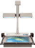
Part Identification and Functions, Head Unit, Lamp Unit, Operation Panel, Book Table, Power Switch
 |
View all Konica Minolta ScanDIVA manuals
Add to My Manuals
Save this manual to your list of manuals |
Page 29 highlights
2 Part Identification and Functions 1 Chapter 2 Overview 2 14 4 5 6 3 7 8 9 10 11 12 13 1. Head Unit: 2. Lamp Unit: 3. Operation Panel: 4. Book Table: 5. Power Switch: 6. Power Cord Socket: 7. USB Connector: 8. Manual Switch Connector: The CCD sensor is housed in this unit. This sensor scans the original. Illuminates the original evenly for accurate scanning. Displays the operation status of the Scanner, and is used to set scanning conditions. Place the original (book, sheet) face up on this table. Enables enhanced scanning of book originals by adjusting to the contours of the book. See pages 4-8 through 4-13 for detailed information and limitations. Turns the Scanner ON/OFF. Plug the Power Cord into this socket. Connect the USB Cable that is supplied with the equipment. Connect the Manual Switch (option). The switch to be used as the "right scan" button should be connected to the left connector of the above figure. The switch to be used as the "left scan" button should be connected to the right connector of the above figure. 2-3
-
 1
1 -
2
-
3
-
4
-
5
-
6
-
7
-
8
-
9
-
10
-
11
-
12
-
13
-
14
-
15
-
16
-
17
-
18
-
19
-
20
-
21
-
22
-
23
-
 24
24 -
 25
25 -
 26
26 -
 27
27 -
 28
28 -
 29
29 -
 30
30 -
 31
31 -
 32
32 -
 33
33 -
 34
34 -
35
-
36
-
37
-
38
-
39
-
40
-
41
-
42
-
43
-
44
-
45
-
46
-
47
-
48
-
49
-
50
-
51
-
52
-
53
-
54
-
55
-
56
-
57
-
58
-
59
-
60
-
61
-
62
-
63
-
64
-
65
-
66
-
67
-
68
-
69
-
70
-
71
-
72
-
73
-
74
-
75
-
76
-
77
-
78
-
79
-
80
-
81
-
82
-
83
-
84
-
85
-
86
-
87
-
88
-
89
-
90
-
91
-
92
-
93
-
94
-
95
-
96
-
97
-
98
-
99
-
100
-
101
-
102
-
103
-
104
 |
 |
