LG LMCN185HV Installation Instructions - Page 17
Ceiling dimension and hanging bolt location - dimensions
 |
View all LG LMCN185HV manuals
Add to My Manuals
Save this manual to your list of manuals |
Page 17 highlights
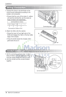
ENGLISH Installation [Cealing Concealed Duct Type] Ceiling dimension and hanging bolt location Installation of Unit Install the unit above the ceiling correctly. B A CASE 1 D C E POSITION OF SUSPENSION BOLT • Apply a joint-canvas between the unit and duct to absorb unnecessary vibration. • Apply a filter Accessory at air return hole. Unit:mm(inch) Dimension Capacity Btu/h class 9/12k ABCDE FGH I 850 900 383 570 93.5 190 20.6 795 163 (33 15/32) (35 15/32) (15 3/32) (22 7/16) (3 11/16) (7 1/2) (13/16) (31 5/16) (6 13/32) 18k 1130 1180 383 570 93.5 190 20.6 1065 163 (44 1/2) (46 1/2) (15 3/32) (22 7/16) (3 11/16) (7 1/2) (13/16) (41 15/16) (6 13/32) G 1/100 H Drainage hole F I CASE 2 • Install the unit leaning to a drainage hole side as a figure for easy water drainage. POSITION OF CONSOLE BOLT • A place where the unit will be leveled and that can support the weight of the unit. • A place where the unit can withstand its vibration. • A place where service can be easily performed. M10 Nut X 4 M10 SP. washer X 4 (Local supply) M10 washer X 4 M10 washer X 4 M10 SP. washer X 4 (Local supply) M10 Nut X 4 Installation Manual 17
-
 1
1 -
2
-
3
-
4
-
5
-
6
-
7
-
8
-
9
-
10
-
11
-
 12
12 -
 13
13 -
 14
14 -
 15
15 -
 16
16 -
 17
17 -
 18
18 -
 19
19 -
 20
20 -
 21
21 -
 22
22 -
23
-
24
-
25
-
26
-
27
-
28
-
29
-
30
-
31
-
32
-
33
-
34
-
35
-
36
-
37
-
38
-
39
-
40
-
41
-
42
-
43
-
44
-
45
-
46
-
47
-
48
-
49
-
50
-
51
-
52
-
53
-
54
-
55
-
56
-
57
-
58
-
59
-
60
-
61
-
62
-
63
-
64
-
65
-
66
-
67
-
68
-
69
-
70
-
71
-
72
-
73
-
74
-
75
-
76
-
77
-
78
-
79
-
80
-
81
-
82
-
83
-
84
-
85
-
86
-
87
-
88
-
89
-
90
-
91
-
92
-
93
-
94
-
95
-
96
-
97
-
98
-
99
-
100
-
101
-
102
-
103
-
104
-
105
-
106
-
107
-
108
-
109
-
110
-
111
-
112
-
113
-
114
-
115
-
116
-
117
-
118
-
119
-
120
-
121
-
122
-
123
-
124
-
125
-
126
-
127
-
128
-
129
-
130
-
131
-
132
-
133
-
134
-
135
-
136
-
137
 |
 |
