LG LMCN185HV Installation Instructions - Page 38
Connect the cable to the Outdoor unit.
 |
View all LG LMCN185HV manuals
Add to My Manuals
Save this manual to your list of manuals |
Page 38 highlights
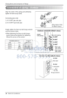
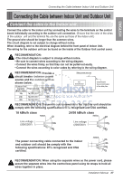
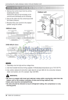
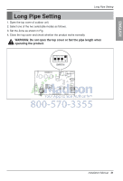
Connecting the Cable between Indoor Unit and Outdoor Unit Connect the cable to the Outdoor unit. 1. Remove the control cover from the unit by loosening the screw. Connect the wires to the terminals on the control board individually as the following. 2. Secure the cable onto the control board with the holder (clamper). 3. Re-attach the cover control to the original position using the screws. Outdoor unit Terminal block Over 5mm (3/16 inch) Holder for power supply cord 18kBtu/h class Indoor Unit Terminal Block A Unit 1(L1) 2(L2) 3 Indoor Unit Terminal Block B Unit 1(L1) 2(L2) 3 Control cover Connecting cable L1 L2 POWER SUPPLY 1(L1) 2(L2) 3(A) 3(B) A UNIT B UNIT 24/36 kBtu/h class Indoor Unit Terminal Block A Unit 1(L1) 2(L2) 3 Indoor Unit Terminal Block B Unit 1(L1) 2(L2) 3 Indoor Unit Terminal Block C Unit 1(L1) 2(L2) 3 36k Only Indoor Unit Terminal Block D Unit 1(L1) 2(L2) 3 Power supply cable L1 L2 POWER SUPPLY 1(L1) 2(L2) 3(A) 3(B) 1(L1) 2(L2) 3(C) 3(D) A UNIT B UNIT C UNIT D UNIT NOTICE : 1. Separately wire the high and low voltage lines. 2. Use heat resistant electrical wiring capable of withstanding temperatures up to 75°C(167°F). 3. Use outdoor waterproof connection cable rated for at least 300V for the connection between indoor and outdoor unit. (For example, Type SJO-WA) WARNING: • Be sure to comply with local and national codes while running the wire from the indoor unit to the outdoor unit(size of wire and wiring method, etc). • Every wire must be connected firmly. • No wire should be allowed to touch refrigerant tubing, the compressor or any moving parts. 38 Multi Air Conditioner
-
 1
1 -
2
-
3
-
4
-
5
-
6
-
7
-
8
-
9
-
10
-
11
-
12
-
13
-
14
-
15
-
16
-
17
-
18
-
19
-
20
-
21
-
22
-
23
-
24
-
25
-
26
-
27
-
28
-
29
-
30
-
31
-
32
-
 33
33 -
 34
34 -
 35
35 -
 36
36 -
 37
37 -
 38
38 -
 39
39 -
 40
40 -
 41
41 -
 42
42 -
 43
43 -
44
-
45
-
46
-
47
-
48
-
49
-
50
-
51
-
52
-
53
-
54
-
55
-
56
-
57
-
58
-
59
-
60
-
61
-
62
-
63
-
64
-
65
-
66
-
67
-
68
-
69
-
70
-
71
-
72
-
73
-
74
-
75
-
76
-
77
-
78
-
79
-
80
-
81
-
82
-
83
-
84
-
85
-
86
-
87
-
88
-
89
-
90
-
91
-
92
-
93
-
94
-
95
-
96
-
97
-
98
-
99
-
100
-
101
-
102
-
103
-
104
-
105
-
106
-
107
-
108
-
109
-
110
-
111
-
112
-
113
-
114
-
115
-
116
-
117
-
118
-
119
-
120
-
121
-
122
-
123
-
124
-
125
-
126
-
127
-
128
-
129
-
130
-
131
-
132
-
133
-
134
-
135
-
136
-
137
 |
 |
