Lenovo 7515-J9U User Guide - Page 34
Replacing the power supply assembly
 |
UPC - 884942137211
View all Lenovo 7515-J9U manuals
Add to My Manuals
Save this manual to your list of manuals |
Page 34 highlights
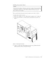
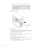
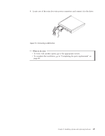
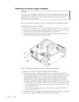
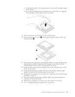
Replacing the power supply assembly Attention Do not open your computer or attempt any repair before reading and understanding the "Important safety information" in the ThinkCentre Safety and Warranty Guide that came with your computer. To obtain a copy of the ThinkCentre Safety and Warranty Guide, go to: http://www.lenovo.com/support This section provides instructions on how to replace the power supply assembly. To replace the power supply assembly: 1. Remove the computer cover. See "Removing the computer cover" on page 14. 2. Disconnect the power supply assembly cables from the system board and all drives. See "Locating parts on the system board" on page 11. 3. Lay the computer on its side and remove the four screws at the rear of the chassis that secure the power supply assembly. 26 User Guide Figure 17. Removing the retaining screws for the power supply assembly 4. Remove the old power supply assembly from the chassis. 5. Ensure that the power supply assembly is the correct replacement. Some power supply assemblies automatically sense the voltage, some power supply assemblies are voltage specific, and some power supply assemblies have a voltage-selection switch. If your computer has a voltage-selection switch, ensure that you set the voltage-selection switch of the new power supply assembly to match the voltage available at your electrical outlet. If necessary, use a ballpoint pen to slide the voltage-selection switch to a different position. v If the voltage supply range in your local country or region is 100-127 V ac, set the switch to 115 V. v If the voltage supply range in your local country or region is 200-240 V ac, set the switch to 230 V. 6. Install the new power supply assembly into the chassis so that the screw holes in the power supply assembly align with those in the chassis.
-
 1
1 -
2
-
3
-
4
-
5
-
6
-
7
-
8
-
9
-
10
-
11
-
12
-
13
-
14
-
15
-
16
-
17
-
18
-
19
-
20
-
21
-
22
-
23
-
24
-
25
-
26
-
27
-
28
-
 29
29 -
 30
30 -
 31
31 -
 32
32 -
 33
33 -
 34
34 -
 35
35 -
 36
36 -
 37
37 -
 38
38 -
 39
39 -
40
-
41
-
42
-
43
-
44
-
45
-
46
-
47
-
48
-
49
-
50
-
51
-
52
-
53
-
54
-
55
-
56
-
57
-
58
-
59
-
60
-
61
-
62
-
63
-
64
-
65
-
66
-
67
-
68
-
69
-
70
-
71
-
72
-
73
-
74
-
75
-
76
-
77
-
78
-
79
-
80
-
81
-
82
-
83
-
84
-
85
-
86
-
87
-
88
-
89
-
90
-
91
-
92
 |
 |
