Lenovo 7515-J9U User Guide - Page 49
mounts through the holes., The new front fan assembly you received will have four new rubber
 |
UPC - 884942137211
View all Lenovo 7515-J9U manuals
Add to My Manuals
Save this manual to your list of manuals |
Page 49 highlights
4. The front fan assembly is attached to the chassis by four rubber mounts. Remove the front fan assembly by breaking or cutting the rubber mounts and gently pulling the front fan assembly out of the chassis. Figure 29. Removing the front fan assembly 5. Install the new front fan assembly by aligning the new rubber mounts of the new front fan assembly with the holes on the chassis and push the rubber mounts through the holes. Note: The new front fan assembly you received will have four new rubber mounts attached. Chapter 2. Installing options and replacing hardware 41
-
 1
1 -
2
-
3
-
4
-
5
-
6
-
7
-
8
-
9
-
10
-
11
-
12
-
13
-
14
-
15
-
16
-
17
-
18
-
19
-
20
-
21
-
22
-
23
-
24
-
25
-
26
-
27
-
28
-
29
-
30
-
31
-
32
-
33
-
34
-
35
-
36
-
37
-
38
-
39
-
40
-
41
-
42
-
43
-
 44
44 -
 45
45 -
 46
46 -
 47
47 -
 48
48 -
 49
49 -
 50
50 -
 51
51 -
 52
52 -
 53
53 -
 54
54 -
55
-
56
-
57
-
58
-
59
-
60
-
61
-
62
-
63
-
64
-
65
-
66
-
67
-
68
-
69
-
70
-
71
-
72
-
73
-
74
-
75
-
76
-
77
-
78
-
79
-
80
-
81
-
82
-
83
-
84
-
85
-
86
-
87
-
88
-
89
-
90
-
91
-
92
 |
 |

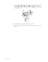
4.
The front fan assembly is attached to the chassis by four rubber mounts.
Remove the front fan assembly by breaking or cutting the rubber mounts and
gently pulling the front fan assembly out of the chassis.
5.
Install the new front fan assembly by aligning the new rubber mounts of the
new front fan assembly with the holes on the chassis and push the rubber
mounts through the holes.
Note:
The new front fan assembly you received will have four new rubber
mounts attached.
Figure 29. Removing the front fan assembly
Chapter 2. Installing options and replacing hardware
41