Lenovo ThinkCentre M91p (English) User Guide - Page 25
Machine type and model label
 |
View all Lenovo ThinkCentre M91p manuals
Add to My Manuals
Save this manual to your list of manuals |
Page 25 highlights
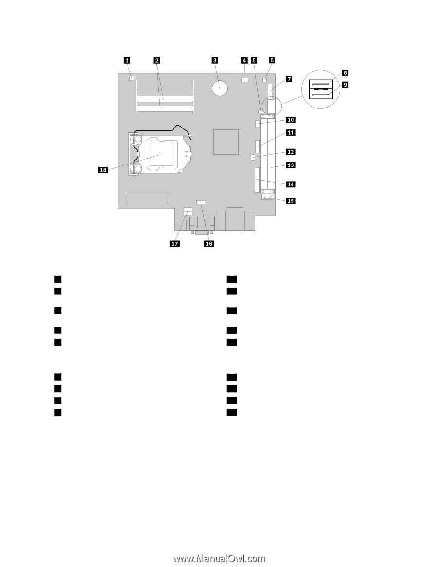
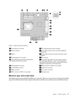
Figure 4. System board part locations 1 Thermal sensor connector 2 Memory slots (2) 3 Battery 4 Microprocessor fan connector 5 Clear CMOS (Complementary Metal Oxide Semiconductor) /Recovery jumper 6 Internal speaker connector 7 Serial (COM2) connector 8 eSATA connector 9 SATA connector 2 (SATA 2.0 connector) 10 PS/2 keyboard and mouse connector 11 Front USB connector 2 (for connecting additional USB devices) 12 Cover presence switch connector (Intrusion switch connector) 13 PCI card slot 14 Front USB, front panel, and front audio connector (for connecting USB ports 1 and 2 on the front bezel, LED indicators and power switch, and microphone and headphone connectors on the front bezel) 15 SATA connector 1 (SATA 3.0 connector) 16 System fan connector 17 4-pin power connector 18 Microprocessor Machine type and model label The machine type and model label identifies your computer. When you contact Lenovo for help, the machine type and model information helps support technicians to identify your computer and provide faster service. Chapter 1. Product overview 11
-
 1
1 -
2
-
3
-
4
-
5
-
6
-
7
-
8
-
9
-
10
-
11
-
12
-
13
-
14
-
15
-
16
-
17
-
18
-
19
-
 20
20 -
 21
21 -
 22
22 -
 23
23 -
 24
24 -
 25
25 -
 26
26 -
 27
27 -
 28
28 -
 29
29 -
 30
30 -
31
-
32
-
33
-
34
-
35
-
36
-
37
-
38
-
39
-
40
-
41
-
42
-
43
-
44
-
45
-
46
-
47
-
48
-
49
-
50
-
51
-
52
-
53
-
54
-
55
-
56
-
57
-
58
-
59
-
60
-
61
-
62
-
63
-
64
-
65
-
66
-
67
-
68
-
69
-
70
-
71
-
72
-
73
-
74
-
75
-
76
-
77
-
78
-
79
-
80
-
81
-
82
-
83
-
84
-
85
-
86
-
87
-
88
-
89
-
90
-
91
-
92
-
93
-
94
-
95
-
96
-
97
-
98
-
99
-
100
-
101
-
102
-
103
-
104
-
105
-
106
-
107
-
108
-
109
-
110
-
111
-
112
-
113
-
114
-
115
-
116
-
117
-
118
-
119
-
120
-
121
-
122
-
123
-
124
-
125
-
126
-
127
-
128
-
129
-
130
 |
 |