Lexmark C540 Service Manual - Page 153
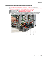
Autocompensator mechanism (ACM) removal-standard tray
 |
View all Lexmark C540 manuals
Add to My Manuals
Save this manual to your list of manuals |
Page 153 highlights
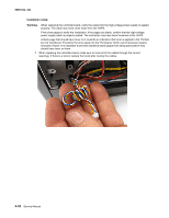
5025-2xx, 4xx Autocompensator mechanism (ACM) removal-standard tray See "Autocompensator mechanism (ACM)-standard tray" on page 7-5 for the part number. 1. Remove the toner cartridges, the waste toner bottle, and the imaging unit (IU). See "Waste toner bottle removal" on page 4-60, and see "Imaging unit (IU) removal" on page 4-35. 2. Remove the left cover. See "Left cover assembly removal" on page 4-6. 3. Remove the rear shield. See "Rear shield removal" on page 4-11. 4. Disconnect the autocompensator mechanism (ACM) cable connector (A) from the controller board. 5. Pull the cable (B) through the opening, and free the cables from the retainers (C) on the left side. Repair information 4-15
-
 1
1 -
2
-
3
-
4
-
5
-
6
-
7
-
8
-
9
-
10
-
11
-
12
-
13
-
14
-
15
-
16
-
17
-
18
-
19
-
20
-
21
-
22
-
23
-
24
-
25
-
26
-
27
-
28
-
29
-
30
-
31
-
32
-
33
-
34
-
35
-
36
-
37
-
38
-
39
-
40
-
41
-
42
-
43
-
44
-
45
-
46
-
47
-
48
-
49
-
50
-
51
-
52
-
53
-
54
-
55
-
56
-
57
-
58
-
59
-
60
-
61
-
62
-
63
-
64
-
65
-
66
-
67
-
68
-
69
-
70
-
71
-
72
-
73
-
74
-
75
-
76
-
77
-
78
-
79
-
80
-
81
-
82
-
83
-
84
-
85
-
86
-
87
-
88
-
89
-
90
-
91
-
92
-
93
-
94
-
95
-
96
-
97
-
98
-
99
-
100
-
101
-
102
-
103
-
104
-
105
-
106
-
107
-
108
-
109
-
110
-
111
-
112
-
113
-
114
-
115
-
116
-
117
-
118
-
119
-
120
-
121
-
122
-
123
-
124
-
125
-
126
-
127
-
128
-
129
-
130
-
131
-
132
-
133
-
134
-
135
-
136
-
137
-
138
-
139
-
140
-
141
-
142
-
143
-
144
-
145
-
146
-
147
-
 148
148 -
 149
149 -
 150
150 -
 151
151 -
 152
152 -
 153
153 -
 154
154 -
 155
155 -
 156
156 -
 157
157 -
 158
158 -
159
-
160
-
161
-
162
-
163
-
164
-
165
-
166
-
167
-
168
-
169
-
170
-
171
-
172
-
173
-
174
-
175
-
176
-
177
-
178
-
179
-
180
-
181
-
182
-
183
-
184
-
185
-
186
-
187
-
188
-
189
-
190
-
191
-
192
-
193
-
194
-
195
-
196
-
197
-
198
-
199
-
200
-
201
-
202
-
203
-
204
-
205
-
206
-
207
-
208
-
209
-
210
-
211
-
212
-
213
-
214
-
215
-
216
-
217
-
218
-
219
-
220
-
221
-
222
-
223
-
224
-
225
-
226
-
227
-
228
-
229
-
230
-
231
-
232
-
233
-
234
-
235
-
236
 |
 |

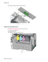
Repair information
4-15
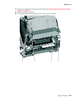
5025-2xx, 4xx
Autocompensator mechanism (ACM) removal—standard tray
See
“Autocompensator mechanism (ACM)—standard tray” on page 7-5
for the part number.
1.
Remove the toner cartridges, the waste toner bottle, and the imaging unit (IU). See
“Waste toner bottle
removal” on page 4-60
, and see
“Imaging unit (IU) removal” on page 4-35
.
2.
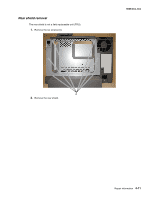
Remove the left cover. See
“Left cover assembly removal” on page 4-6
.
3.
Remove the rear shield. See
“Rear shield removal” on page 4-11
.
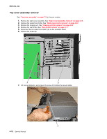
4.
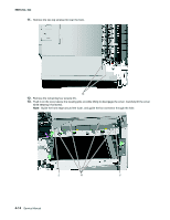
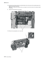
Disconnect the autocompensator mechanism (ACM) cable connector (A) from the controller board.
5.
Pull the cable (B) through the opening, and free the cables from the retainers (C) on the left side.