Lexmark C540 Service Manual - Page 68
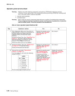
Input sensor (S2) service check, 2xx, 4xx, Questions / actions, Base Sensor Test, Select
 |
View all Lexmark C540 manuals
Add to My Manuals
Save this manual to your list of manuals |
Page 68 highlights
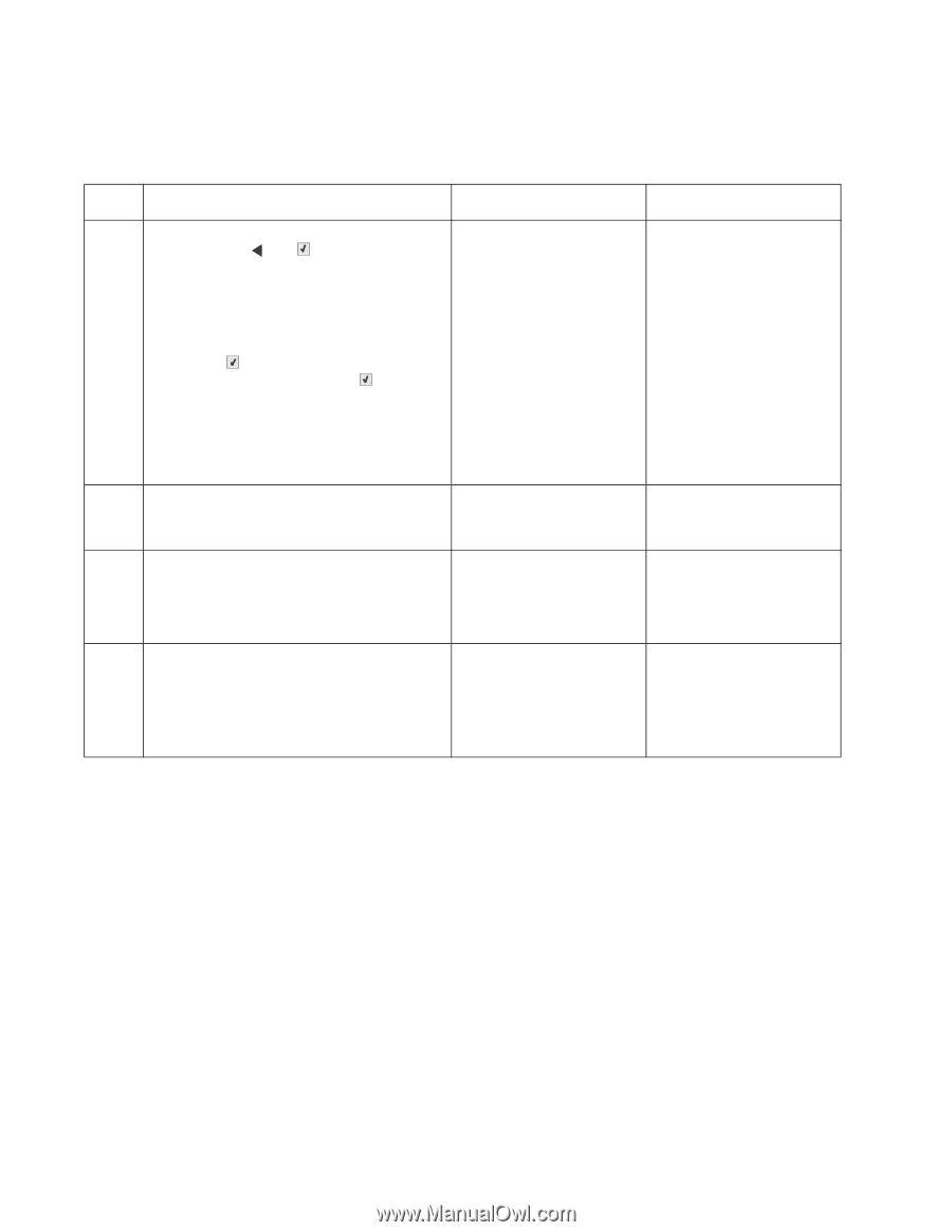
5025-2xx, 4xx Input sensor (S2) service check The Input sensor (S2) is part of the ACM FRU. Step Questions / actions Yes 1 Enter Diagnostics Menu (turn the printer off, press and hold and , turn the printer on, and then release the buttons when the installed memory and processor speed displays). Perform the Base Sensor Test. See "Base Sensor Test" on page 3-16. 1. Select Base Sensor Test, and press Select ( ). 2. Select S2, and press Select ( ). 3. Pull tray 1 out, and rotate the S2 sensor flag (S2 is located in front of the center autocompensator mechanism housing.) It should rotate freely and return to its original position. Is the input (S2) sensor flag damaged? Replace the autocompensator mechanism. See "Autocompensator mechanism (ACM) removal-standard tray" on page 4-15. 2 Watch the display while rotating the flag. Does the display indicate Media Clear and Media Present? 3 Turn the printer off, and remove the rear shield. See "Rear shield removal" on page 4-11. Is the JSP1 cable connector properly connected to the controller board? Problem resolved. Go to step 4. 4 Turn the printer on, and check the voltage at JSP1 pin 15. Is the voltage approximately +5 V dc? Replace the autocompensator mechanism. See "Autocompensator mechanism (ACM) removal-standard tray" on page 4-15. No Go to step 2. Go to step 3. Reseat the connector. Replace the controller board. See "Controller board removal" on page 4-19. 2-34 Service Manual
-
 1
1 -
2
-
3
-
4
-
5
-
6
-
7
-
8
-
9
-
10
-
11
-
12
-
13
-
14
-
15
-
16
-
17
-
18
-
19
-
20
-
21
-
22
-
23
-
24
-
25
-
26
-
27
-
28
-
29
-
30
-
31
-
32
-
33
-
34
-
35
-
36
-
37
-
38
-
39
-
40
-
41
-
42
-
43
-
44
-
45
-
46
-
47
-
48
-
49
-
50
-
51
-
52
-
53
-
54
-
55
-
56
-
57
-
58
-
59
-
60
-
61
-
62
-
 63
63 -
 64
64 -
 65
65 -
 66
66 -
 67
67 -
 68
68 -
 69
69 -
 70
70 -
 71
71 -
 72
72 -
 73
73 -
74
-
75
-
76
-
77
-
78
-
79
-
80
-
81
-
82
-
83
-
84
-
85
-
86
-
87
-
88
-
89
-
90
-
91
-
92
-
93
-
94
-
95
-
96
-
97
-
98
-
99
-
100
-
101
-
102
-
103
-
104
-
105
-
106
-
107
-
108
-
109
-
110
-
111
-
112
-
113
-
114
-
115
-
116
-
117
-
118
-
119
-
120
-
121
-
122
-
123
-
124
-
125
-
126
-
127
-
128
-
129
-
130
-
131
-
132
-
133
-
134
-
135
-
136
-
137
-
138
-
139
-
140
-
141
-
142
-
143
-
144
-
145
-
146
-
147
-
148
-
149
-
150
-
151
-
152
-
153
-
154
-
155
-
156
-
157
-
158
-
159
-
160
-
161
-
162
-
163
-
164
-
165
-
166
-
167
-
168
-
169
-
170
-
171
-
172
-
173
-
174
-
175
-
176
-
177
-
178
-
179
-
180
-
181
-
182
-
183
-
184
-
185
-
186
-
187
-
188
-
189
-
190
-
191
-
192
-
193
-
194
-
195
-
196
-
197
-
198
-
199
-
200
-
201
-
202
-
203
-
204
-
205
-
206
-
207
-
208
-
209
-
210
-
211
-
212
-
213
-
214
-
215
-
216
-
217
-
218
-
219
-
220
-
221
-
222
-
223
-
224
-
225
-
226
-
227
-
228
-
229
-
230
-
231
-
232
-
233
-
234
-
235
-
236
 |
 |