LiftMaster Icon 26 ICON26 Manual
LiftMaster Icon 26 Manual
|
View all LiftMaster Icon 26 manuals
Add to My Manuals
Save this manual to your list of manuals |
LiftMaster Icon 26 manual content summary:
- LiftMaster Icon 26 | ICON26 Manual - Page 1
- LiftMaster Icon 26 | ICON26 Manual - Page 2
Resident Information 25 Transmitter/Card Programming 26 Area Codes 27 Controller Board 37 Large Display Battery Back-Up 38 Auxiliary Input/Output 39 Optional Camera 40 Parts List and Part Illustrations 41 Approvals 42 To be installed by Qualified Dealers ONLY! Icon Page 1 Icon26 manual - LiftMaster Icon 26 | ICON26 Manual - Page 3
Icon Page 2 - LiftMaster Icon 26 | ICON26 Manual - Page 4
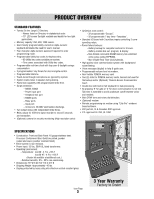
250, 500, 1000 names. • User-friendly programmability via built-in alpha-numeric keyboard eliminates the need for user's manual. • Four character alpha-numeric password required to enter programming mode. • Programmable Utility key codes for keyless entry. - 60 Utility key codes available per system - LiftMaster Icon 26 | ICON26 Manual - Page 5
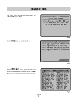
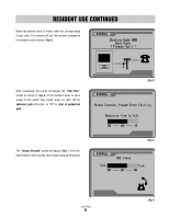
Icon26 System will start and default back to the "Welcome To" screen (fig a.). Use the button for assistance. (fig b.). (fig a.) Use the keys to access the residence list in the Icon26's electronic directory as shown in (fig c.). The names are listed in alphabetical order by last name. Icon - LiftMaster Icon 26 | ICON26 Manual - Page 6
found, enter the corresponding 3-digit code. The system will dial the number assigned to the resident code entered. (fig d.) STATUS After connecting, the screen will display the "Talk Time" screen as shown in (fig e.) If the resident wants to allow access to the visitor, they simply press (or dial - LiftMaster Icon 26 | ICON26 Manual - Page 7
ENTRY ONLY) RESIDENT 6-DIGIT KEY CODES Residents are assigned a 6-digit, personalized key code for accessing the facility. To use the key code assigned, the resident must first push the key once and enter their key code. The screen will display "Access Granted" (fig a.) and access - LiftMaster Icon 26 | ICON26 Manual - Page 8
All systems, no matter what the memory capacity, are equipped with 60 different Utility codes. To access the facility within the time zone set, the Utility Company must first press the key TWICE and then enter their 4- digit code. If it is within the programmed time zone for entry, the screen - LiftMaster Icon 26 | ICON26 Manual - Page 9
Icon26 FEATURES (INSIDE) Processor Key Release / Lock Mounting Holes (4) Processor Power Switch Power Backup Unit Large Display Large Display Power Switch Contrast Adjustment Microphone Camera (Optional) Cooling Fan Memory Card Release Buttons Memory Card Memory Card Slot LC Display Knock - LiftMaster Icon 26 | ICON26 Manual - Page 10
10 HANG-UP KEY - Pressed when user wants to hang up. 9 11 ACCESS FOR POSTAL LOCK 10 4 11 12 16 GAUGE STAINLESS STEEL DOOR Heavy-duty and weather resistant. 12 13 CAMERA (OPTIONAL) - For security monitoring. All components and specifications are subject to change without notice. Icon Page 9 - LiftMaster Icon 26 | ICON26 Manual - Page 11
Icon26 FEATURES (PROCESSOR) 1000 500 250 1 4 5 Main Memory Card Slot 6 RS485 Memory Card Slot Remote Access RS485 COMMUNICATOR CARD capacity 2 1 MEMORY CARD - Stores all programmed information. (Different memory sizes available) 2 COMMUNICATOR CARD - Card for RS485 devices. 3 POWER ON/OFF - LiftMaster Icon 26 | ICON26 Manual - Page 12
manual for Chamberlain Elite instructions before installating and operating any Chamberlain Elite products. Chamberlain Elite is not responsible for improper installations or failure to comply with local building codes. All components and specifications are subject to change without notice. Icon - LiftMaster Icon 26 | ICON26 Manual - Page 13
activates auxiliary Relay 2 2 POWER IN: 12 Vac to the Entry Phone. CHASSIS GROUND 8 3 TELEPHONE LINE: Tip and Ring Connection. POSTAL/ EXIT VCR SWITCH INPUT RELAY 9 10 CAMERA 11 4 GATE RELAY: For use with gate operator to control access through main vehicular gate. 5 DOOR RELAY: For allowing - LiftMaster Icon 26 | ICON26 Manual - Page 14
V-C V-NO COM NO COM NC NO GATE DOOR RE A R LAY VIDEO OUT HASS S ROUND CAMERA FAN KBRD L GHT AUX 1 RE AY AUX 2 R LAY GATE DOOR RELAY RE AY P W R Ground Rod Refer to the next page for ground rod installation. Icon Page 13 It is MANDATORY that this unit is properly grounded. The - LiftMaster Icon 26 | ICON26 Manual - Page 15
other underground utility lines. to the "Chassis Ground" of Telephone Entry System The earth ground rod must be located within 3 feet from the Telephone Entry System. For the correct wire gauge, consult the local code building codes. For the correct diameter, consult the local code Icon Page 14 - LiftMaster Icon 26 | ICON26 Manual - Page 16
RING COM NC NO COM NC NO GATE DOOR RELAY RELAY VIDEO OUT CHASSIS GROUND CAMERA TIP RING Transformer Telephone Line: 12 Vac (50VA) (Provided) MUST be a dedicated line for the Telephone Entry System unit ONLY! NOTE: Installation where fiber optic phone lines are present Polarity does not - LiftMaster Icon 26 | ICON26 Manual - Page 17
the "LCD power" switch on the battery back-up module. 2. Turn on processor using the power switch on the top right. 3. To turn unit off, turn off both processor and large display battery back-up module. Large Display Power Switch Be sure to read and follow all Chamberlain Elite instructions before - LiftMaster Icon 26 | ICON26 Manual - Page 18
RELAY VIDEO OUT CHASSIS GROUND CAMERA It is MANDATORY that this unit is properly grounded. The provided "chassis ground" wire must be connected to the ground rod. If unit is not grounded, lightning damage Installation: 1 Open the front panel of the Telephone Entry System and remove the hole plug - LiftMaster Icon 26 | ICON26 Manual - Page 19
for superior data transmission) • Up to 31 RS485 devices supported • Maximum distance from the last RS485 device to the Telephone Entry System is 4000 Ft. • Turn "ON" the terminator switch ONLY by using the rotary switches on the device. (Refer to specific RS485 Instruction sheets). Icon Page 18 - LiftMaster Icon 26 | ICON26 Manual - Page 20
Access RS485 COMMUNICATOR CARD capacity Main M ard Slot RS485 Memory Card Slot RS485 Card Release Button NOTE: To support RS485 devices you must insert the RF communicator card in the RS485 memory card GROUND CAMERA Card Reader RS485 Remote Device 3 Icon Page 19 Universal Interface Board - LiftMaster Icon 26 | ICON26 Manual - Page 21
Access RS485 COMMUNICATOR CARD capacity Main M Card Slot RS485 Memory Card Slot RS485 Card Release Button NOTE: To support RS485 devices you must insert the RF communicator card in the RS485 memory card GATE DOOR RELAY RELAY VIDEO OUT CHASSIS GROUND CAMERA It i MANDATOR hat s unit is properly - LiftMaster Icon 26 | ICON26 Manual - Page 22
an information screen is accessible on all Dial Code systems for easy reference. Turn power off and insert Memory Card in Main Memory Slot. Turn power on and the information screen should display as seen in (fig e.) DIAL CODE LC-250 REV. 1.00_ (fig e.) Software Version Number Icon Page 21 - LiftMaster Icon 26 | ICON26 Manual - Page 23
not touch the terminals on the RAM Cards. Do not bend, drop or expose to impact. ENTER ERASE EXIT Q PROGRAM E W S R D SHIFT A Z X SPACE BAR 3 1 4 2 5 8 6 9 7 0 I HELP T U Y J H G N F B V C O K M P L BSAPACCKE ' The Telephone Entry System is only water resistant when the - LiftMaster Icon 26 | ICON26 Manual - Page 24
PROG MODE: (N)Names (U)Utility If you enter the wrong password, the screen will prompt you to try again: INVALID PASSWORD (R)Retry (EXIT)Quit Press R to retry entering your password. Press to quit the programming menu. Pressing the button will provide users with a help message. Icon Page 23 - LiftMaster Icon 26 | ICON26 Manual - Page 25
System Clock and Seven Day Timers S Program relay output time ( for 2 relays ) T Program length of Talk Time G Program custom Welcome Screen Message V Program Volume level B Backup of memory card NOTE: While in the help screens, programming will be disabled. To continue programming, press the - LiftMaster Icon 26 | ICON26 Manual - Page 26
Resident phone number (fig d.). If you need to enter an area code refer to the area code page. Press the key to complete the entry. The "KEY CODE" screen will be displayed. (fig e.) 5 STEP 005 KEY CODE: An individual six digit Resident Key code may be assigned to each resident . Residents - LiftMaster Icon 26 | ICON26 Manual - Page 27
8 for up to ten devices per directory code. After the last device has been programmed, press or key to return to the program selection screen. NOTE: The time zones and restrictions associated with transmitter/card codes can only be programmed remotely using the EMS modem software. Icon Page 26 - LiftMaster Icon 26 | ICON26 Manual - Page 28
field followed by the phone number. Press the key to continue with the entry as described in the "Resident Information" section. To erase "Resident" in the help screens, programming will be disabled. To continue programming, press the button to exit the help screens first. Icon Page 27 - LiftMaster Icon 26 | ICON26 Manual - Page 29
only) may be assigned to "Utility Companies" such as delivery, telephone, construction companies, water, power, etc. These utilities can use their individual code to access the premises within the time zone that you program. Each system, no matter what the memory capacity, is equipped with 60 - LiftMaster Icon 26 | ICON26 Manual - Page 30
that you customize it. In the Program Selection Screen (fig a.), Press the P key. To customize To leave the password unchanged, press the key.) A confirmation screen will appear (fig c.). Type in the same password and the help screens, programming will be disabled. To continue programming, press - LiftMaster Icon 26 | ICON26 Manual - Page 31
, auto leap year compensation and daylight savings. In the Program Selection Screen (fig a.), Press the C key. Use the keys to scroll savings by pressing Y for yes or N for no. The key will complete the date and time entry. (fig e.) SELECT PROG MODE: (C)Clock/Timer (fig a.) PROG CLOCK/ - LiftMaster Icon 26 | ICON26 Manual - Page 32
Menu. Setup New Timers> N View/Edit Timers> See next page for instructions USE ARROWS TO VIEW / PROGRAM INDIVIDUAL TIME ZONES Use to view and program key when complete. To exit "Timers" screen, press the key. Press the key for assistance. IMPORTANT NOTE: While in the help screens, programming - LiftMaster Icon 26 | ICON26 Manual - Page 33
TIME ZONES See previous page for instructions Program timers 1 and 2 for above procedure. Press the key when complete. GATE Tmr2: ON F=off __ week. Press when complete. (fig e.) COPY Timers1,2 To screen, press the key. Press the key for assistance. IMPORTANT NOTE: While in the help screens - LiftMaster Icon 26 | ICON26 Manual - Page 34
Press the key to complete the transaction. TALK TIME You can set the amount of time to talk on the Entry Phone at 20, Screen (fig g.), Press the T key. Choose the desired Talk Time, press A for 20 seconds, B for 40 seconds, or C for 80 seconds (fig h.). Press the key to confirm your entry. Icon - LiftMaster Icon 26 | ICON26 Manual - Page 35
of the facility and press the key to complete your entry. The system will automatically center your entry on the Welcome screen.(fig b.) SELECT PROG MODE: (G)Greeting (fig a.) FACILITY NAME: Woodbridge Meadows (fig b.) VOLUME ADJUST Use the Volume Screen to adjust both call and unit message volume - LiftMaster Icon 26 | ICON26 Manual - Page 36
MEMORY Main Memory Card Slot RS485 Memory Card Slot Back-Up Memory Card Release Button In the Program Selection Screen (fig b.), Press the B key. Insert additional memory card in the Backup Slot. NOTE: Back-up Memory card must be the same size or greater than the Main Memory card being backed up - LiftMaster Icon 26 | ICON26 Manual - Page 37
message is displayed. (fig a.) Codes that cannot be accessed by the limitation of the system being used cannot be edited. Codes Detected out of Range, See Manual (fig a.) LOW BATTERY If the battery backup is reaching it's minimal charge level, a battery icon with a "B" next to it will display in - LiftMaster Icon 26 | ICON26 Manual - Page 38
DISPLAY CONTROLLER BOARD System has no power (Transformer, Battery). 10 OVRV ON: Incorrect transformer voltage (Overvoltage). OFF: Proper transformer voltage (Transformer plugged in). 11 Busy ON: LED flashes when receiving data from processor. OFF: No data being received from processor. Icon - LiftMaster Icon 26 | ICON26 Manual - Page 39
LARGE DISPLAY BATTERY BACK-UP OVRV BUSY T-100 is a built-in battery back-up module for the Large Display Controller Board. It provides the system with 3 to 5 hours of battery operation. NOTE: "LCD Power" switch must always be turned ON for large display to operate. Icon Page 38 - LiftMaster Icon 26 | ICON26 Manual - Page 40
RELAY RELAY VIDEO OUT CHASSIS GROUND CAMERA It is MANDATORY that this unit is properly i und" Auxiliary inputs can be used for Postal Lock and/or Exit switch operations. Wiring Instructions: 1 Connect one terminal of a 2 are equal to the programmable "Door Strike Time" of processor Icon Page 39 - LiftMaster Icon 26 | ICON26 Manual - Page 41
OPTIONAL CAMERA 1 Part # ICON26CAMERA This compact, optional color camera is only 22 mm x 26 mm and is capable of 10-bit DSP, 330 line resolution output. 1 Connect camera to surge suppression terminal board with cable supplied with camera. 2 Connect a BNC cable from a time lapse recorder or monitor - LiftMaster Icon 26 | ICON26 Manual - Page 42
Sensor Cable (GLCD) Icon Fan (Surge Protection Terminal) Icon Surge Protection Board Icon Display HT W/ Control Board 25 Name Memory Card 50 Name Memory Card 150 Name Memory Card 250 Name Memory Card 500 Name Memory Card 1000 Name Memory Card All components and specifications are subject to change - LiftMaster Icon 26 | ICON26 Manual - Page 43
The Chamberlain Group, Inc. Complies with Part 68, FCC Rules FCC Part 15 - Tested to comply with FCC standards for home or office use This Class B digital apparatus meets all requirements of CANADIAN Interference Causing Equipment Regulations. UL STD 294, 5th Ed. UL STD 1950, 3rd Ed. Instruction - LiftMaster Icon 26 | ICON26 Manual - Page 44
114A2894E © 2008 The Chamberlain Group, Inc. - All Rights Reserved 845 Larch Avenue Elmhurst, Illinois 60126-1196
-
 1
1 -
 2
2 -
 3
3 -
 4
4 -
 5
5 -
 6
6 -
 7
7 -
8
-
9
-
10
-
11
-
12
-
13
-
14
-
15
-
16
-
17
-
18
-
19
-
20
-
21
-
22
-
23
-
24
-
25
-
26
-
27
-
28
-
29
-
30
-
31
-
32
-
33
-
34
-
35
-
36
-
37
-
38
-
39
-
40
-
41
-
42
-
43
-
44
 |
 |