LiftMaster Icon 26 ICON26 Manual - Page 18
Postal Lock Installation
|
View all LiftMaster Icon 26 manuals
Add to My Manuals
Save this manual to your list of manuals |
Page 18 highlights
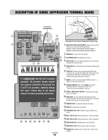
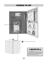
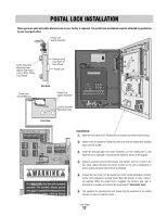
POSTAL LOCK INSTALLATION These parts are used only when postal access to your facility is required. The postal lock mechanism must be obtained by application to your local post office. Postal Lock Switch Assembly Switch Assembly Mounting Holes (Mount with Postal Lock on Entry Phone Front Panel) Stainless Steel Front Panel of Entry Phone Postal Lock Postal Lock Switch Wires (2) Side View Postal Lock Switch Assembly Switch Assembly Mounting Holes BRD AU AN L GHT RE AUX 2 GA E OR R LAY R LAY RE AY Front View 2-NO 2-NC 2-COM 1-NO 1-NC 1-COM GND 2-IN 1-IN AUX OUTPUT RELAYS (+) 12V AUX AC/DC INPUT POWER IN (+) (-) (-) GND GND RS-485 (3) RS-485 (1) TIP RING (+) (-) GND RS-485 (4) (+) (-) GND RS-485 (2) IN GND V-C V-NO TEL LINE IN POSTAL/ EXIT VCR SWITCH INPUT RELAY COM NC NO COM NC NO GATE DOOR RELAY RELAY VIDEO OUT CHASSIS GROUND CAMERA It is MANDATORY that this unit is properly grounded. The provided "chassis ground" wire must be connected to the ground rod. If unit is not grounded, lightning damage Installation: 1 Open the front panel of the Telephone Entry System and remove the hole plug. 2 (Retain nuts and washers) Install the postal lock with the sliding bolt oriented away from the speaker. 3 Install the enclosed plate end switch assembly over the sliding bolt so that when the bolt is extended it will activate the switch as shown in the diagram. 4 Fasten by using the enclosed flat washer, lock washer, and nut on each of the four studs. Adjust the plate and switch location as the nuts are tightened to ensure switch activation when the bolt is extended. 5 Connect the two wires from the postal lock switch to the postal/exit connector on the surge suppressor terminal board. Note that polarity or color coding is not required. When the postal lock is engaged, the system's gate relay is activated for a duration according to the programmed "Gate Strike Time". 6 Test operation by activating the lock. Ensure that full extension of the sliding bolt will not bend or break the switch. Icon Page 17
-
 1
1 -
2
-
3
-
4
-
5
-
6
-
7
-
8
-
9
-
10
-
11
-
12
-
 13
13 -
 14
14 -
 15
15 -
 16
16 -
 17
17 -
 18
18 -
 19
19 -
 20
20 -
 21
21 -
 22
22 -
 23
23 -
24
-
25
-
26
-
27
-
28
-
29
-
30
-
31
-
32
-
33
-
34
-
35
-
36
-
37
-
38
-
39
-
40
-
41
-
42
-
43
-
44
 |
 |