LiftMaster Icon 26 ICON26 Manual - Page 21
Rs485 Star Connection Example
|
View all LiftMaster Icon 26 manuals
Add to My Manuals
Save this manual to your list of manuals |
Page 21 highlights
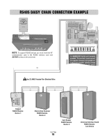
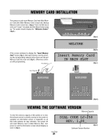
RS485 STAR CONNECTION EXAMPLE 2-NO 2-NC 2-COM 1-COM GND 2-IN 1-IN Remote Access RS485 COMMUNICATOR CARD capacity Main M Card Slot RS485 Memory Card Slot RS485 Card Release Button NOTE: To support RS485 devices you must insert the RF communicator card in the RS485 memory card slot BEFORE turning on the processor. Gnd - + AU OUTPUT ) ) RS485 (3) 12V AUX AC/DC YS INPUT POWER IN (+) (-) GND RS485 (1) () () ND RS485 (4) (+) (-) GND RS485 (2) TE NE IN POSTAL/ E VCR SWITCH INP RELA IN GN V-C V NO COM NC NO COM NC NO GATE DOOR RELAY RELAY VIDEO OUT CHASSIS GROUND CAMERA It i MANDATOR hat s unit is properly gro ded. The p vide "chassis ground" wi must be con cte o the ground rod. If u t is not gro ded ightning damage r to the owners Gnd - + Gnd + - - + Gnd Keypad RS485 Remote Device 3 Stand-Alone Receiver RS485 Remote Device 4 Use 22 AWG Twisted Pair Shielded Wire Card Reader RS485 Remote Device 2 Icon Page 20 Universal Interface Board RS485 Remote Device 1
-
 1
1 -
2
-
3
-
4
-
5
-
6
-
7
-
8
-
9
-
10
-
11
-
12
-
13
-
14
-
15
-
 16
16 -
 17
17 -
 18
18 -
 19
19 -
 20
20 -
 21
21 -
 22
22 -
 23
23 -
 24
24 -
 25
25 -
 26
26 -
27
-
28
-
29
-
30
-
31
-
32
-
33
-
34
-
35
-
36
-
37
-
38
-
39
-
40
-
41
-
42
-
43
-
44
 |
 |