LiftMaster Icon 26 ICON26 Manual - Page 16
Basic Wiring Diagram, Or - software
|
View all LiftMaster Icon 26 manuals
Add to My Manuals
Save this manual to your list of manuals |
Page 16 highlights
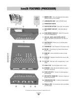
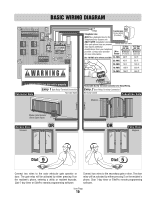
BASIC WIRING DIAGRAM 2-NO 2-NC 2-COM 1-NO 1-NC 1-COM GND 2-IN 1-IN AUX OUTPUT RELAYS (+) AUX INPUT (+) 12V AC/DC POWER IN (-) (-) GND GND RS-485 (3) RS-485 (1) (+) (-) GND RS-485 (4) (+) (-) GND RS-485 (2) IN GND V-C V-NO TEL LINE IN POSTAL/ EXIT VCR SWITCH INPUT RELAY TIP RING COM NC NO COM NC NO GATE DOOR RELAY RELAY VIDEO OUT CHASSIS GROUND CAMERA TIP RING Transformer Telephone Line: 12 Vac (50VA) (Provided) MUST be a dedicated line for the Telephone Entry System unit ONLY! NOTE: Installation where fiber optic phone lines are present Polarity does not matter may require additional modifications from your telephone provider. Contact your provider for more information. Wire Gauge 12 Vac (50 VA) Maximum Distance (Provided) 16.5 Vac (50 VA) Maximum Distance (Optional) Use 18 AWG wire where possible 24 AWG 30 Ft 50 Ft 22 AWG 45 Ft 85 Ft 20 AWG 75 Ft 135 Ft 18 AWG 125 Ft 220 Ft 16 AWG 185 Ft 345 Ft A1C2VDC POWER IN It is MANDATORY that this unit is properly Vehicular Gate Entry 1 Gate Relay Terminal Connection Normally Open Removable Screw Terminal Connectors for Easy Wiring. Entry 2 Door Relay Terminal Connection Normally Closed Pedestrian Gate Maglock Conduit Conduit Master Gate Operator (Strike Open Input) Access Door Solenoid OR OR Entry Door Maglock Dial Dial Connect two wires to the main vehicular gate operator or door. The gate relay will be activated by either pressing 9 on the resident's phone, entering a utility or resident keycode, Gate 7-day timer or ElitePro remote programming software. Connect two wires to the secondary gate or door. The door relay will be activated by either pressing 5 on the resident's phone, Door 7-day timer or ElitePro remote programming software. Icon Page 15
-
 1
1 -
2
-
3
-
4
-
5
-
6
-
7
-
8
-
9
-
10
-
 11
11 -
 12
12 -
 13
13 -
 14
14 -
 15
15 -
 16
16 -
 17
17 -
 18
18 -
 19
19 -
 20
20 -
 21
21 -
22
-
23
-
24
-
25
-
26
-
27
-
28
-
29
-
30
-
31
-
32
-
33
-
34
-
35
-
36
-
37
-
38
-
39
-
40
-
41
-
42
-
43
-
44
 |
 |