LiftMaster Icon 26 ICON26 Manual - Page 40
Auxiliary Input/output Connections
|
View all LiftMaster Icon 26 manuals
Add to My Manuals
Save this manual to your list of manuals |
Page 40 highlights
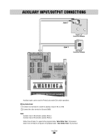
AUXILIARY INPUT/OUTPUT CONNECTIONS Input 2 Postal Lock Connection Example 1-IN 2-IN GND Input 1 Exit Switch Connection Example 1-IN 2-IN GND 1-COM 1-NC 1-NO 2-COM 2-NC 2-NO AUX AUX 12V AC/DC OUTPUT RELAYS (+) INPUT POWER IN (+) (-) (-) GND GND RS-485 (3) RS-485 (1) (+) (-) GND RS-485 (4) (+) (-) GND RS-485 (2) TEL LINE IN POSTAL/ EXIT VCR SWITCH INPUT RELAY IN GND V-C V-NO COM NC NO COM NC NO GATE DOOR RELAY RELAY VIDEO OUT CHASSIS GROUND CAMERA It is MANDATORY that this unit is properly i und" Auxiliary inputs can be used for Postal Lock and/or Exit switch operations. Wiring Instructions: 1 Connect one terminal of a switch to Auxiliary Input (1-IN, or 2-IN) 2 Connect the other terminal to Ground (GND). Note: Auxiliary Input 1-IN activates auxiliary Relay 1 Auxiliary Input 2-IN activates auxiliary Relay 2 Strike Time of Relay 1 is equal to the programmable "Gate Strike Time" of processor Strike Time of Relay 2 are equal to the programmable "Door Strike Time" of processor Icon Page 39
-
 1
1 -
2
-
3
-
4
-
5
-
6
-
7
-
8
-
9
-
10
-
11
-
12
-
13
-
14
-
15
-
16
-
17
-
18
-
19
-
20
-
21
-
22
-
23
-
24
-
25
-
26
-
27
-
28
-
29
-
30
-
31
-
32
-
33
-
34
-
 35
35 -
 36
36 -
 37
37 -
 38
38 -
 39
39 -
 40
40 -
 41
41 -
 42
42 -
 43
43 -
 44
44
 |
 |