LiftMaster Icon 26 ICON26 Manual - Page 41
Optional Camera
|
View all LiftMaster Icon 26 manuals
Add to My Manuals
Save this manual to your list of manuals |
Page 41 highlights
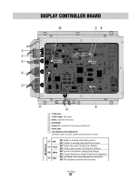
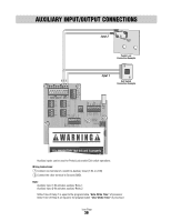
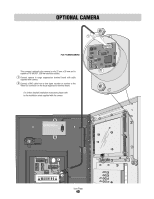
OPTIONAL CAMERA 1 Part # ICON26CAMERA This compact, optional color camera is only 22 mm x 26 mm and is capable of 10-bit DSP, 330 line resolution output. 1 Connect camera to surge suppression terminal board with cable supplied with camera. 2 Connect a BNC cable from a time lapse recorder or monitor to the Video Out connector on the surge suppression terminal board. For further detailed installation instructions please refer to the installation sheet supplied with the camera. 2-NO 2-NC 2-COM 1-NO 1-NC 1-COM GND 2-IN 1-IN AUX OUTPUT RELAYS (+) AUX NPUT (+) 12V AC DC POWER IN () () GND GND RS 485 (3) RS 485 (1) (+) () GND RS 485 (4) (+) () GND RS 485 (2) TEL LINE IN N GND V-C V-NO COM NC NO COM NC NO 2 GATE RELAY DOOR RELAY VIDEO OUT CHASSIS GROUND POSTAL/ EXIT VCR CAMERA SWITCH INPUT RELAY 1 Icon Page 40
-
 1
1 -
2
-
3
-
4
-
5
-
6
-
7
-
8
-
9
-
10
-
11
-
12
-
13
-
14
-
15
-
16
-
17
-
18
-
19
-
20
-
21
-
22
-
23
-
24
-
25
-
26
-
27
-
28
-
29
-
30
-
31
-
32
-
33
-
34
-
35
-
 36
36 -
 37
37 -
 38
38 -
 39
39 -
 40
40 -
 41
41 -
 42
42 -
 43
43 -
 44
44
 |
 |