LiftMaster Icon 26 ICON26 Manual - Page 14
Grounding The Unit
|
View all LiftMaster Icon 26 manuals
Add to My Manuals
Save this manual to your list of manuals |
Page 14 highlights
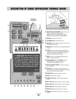
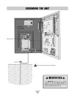
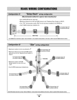
GROUNDING THE UNIT -NO -NC -COM -NO -NC -COM ND -N Chassis Ground 12V AUX AUX AC/DC OUTPUT RELAYS NPUT POWER N +) +) -) -) GND GND RS 485 3) RS 485 (1) +) -) GND RS 485 4) +) -) GND RS 485 (2) TEL L NE N N GND V-C V-NO COM NO COM NC NO GATE DOOR RE A R LAY VIDEO OUT HASS S ROUND CAMERA FAN KBRD L GHT AUX 1 RE AY AUX 2 R LAY GATE DOOR RELAY RE AY P W R Ground Rod Refer to the next page for ground rod installation. Icon Page 13 It is MANDATORY that this unit is properly grounded. The provided "chassis ground" wire must be connected to the ground rod. If unit is not grounded, lightning damage will occur.
-
 1
1 -
2
-
3
-
4
-
5
-
6
-
7
-
8
-
 9
9 -
 10
10 -
 11
11 -
 12
12 -
 13
13 -
 14
14 -
 15
15 -
 16
16 -
 17
17 -
 18
18 -
 19
19 -
20
-
21
-
22
-
23
-
24
-
25
-
26
-
27
-
28
-
29
-
30
-
31
-
32
-
33
-
34
-
35
-
36
-
37
-
38
-
39
-
40
-
41
-
42
-
43
-
44
 |
 |
13
Icon Page
GROUNDING THE UNIT
+)
-)
GND
+)
-)
GND
+)
-)
GND
N
GND
V-C
V-NO
+)
-)
GND
COM
NO
-NO
-NC
-COM
-NO
-NC
-COM
ND
-N
COM
NC
NO
RS 485 4)
RS 485 3)
AUX
OUTPUT RELAYS
AUX
NPUT
12V
AC/DC
RS 485 (2)
FAN
KBRD
L GHT
AUX 1
RE AY
AUX 2
R LAY
GATE
RELAY
DOOR
RE AY
PWR
POWER N
TEL L NE N
RS 485 (1)
GATE
RE A
DOOR
R LAY
HASS S
ROUND
CAMERA
VIDEO
OUT
Chassis Ground
Ground Rod
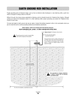
Refer to the next page for ground rod installation.
It is
MANDATORY
that this unit is properly
grounded. The provided
"chassis ground"
wire
must
be connected to the ground rod. If unit is not
grounded, lightning damage will occur.