LiftMaster Icon 26 ICON26 Manual - Page 11
Icon26 Features (processor - access control
|
View all LiftMaster Icon 26 manuals
Add to My Manuals
Save this manual to your list of manuals |
Page 11 highlights
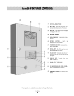
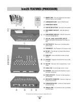
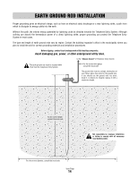
Icon26 FEATURES (PROCESSOR) 1000 500 250 1 4 5 Main Memory Card Slot 6 RS485 Memory Card Slot Remote Access RS485 COMMUNICATOR CARD capacity 2 1 MEMORY CARD - Stores all programmed information. (Different memory sizes available) 2 COMMUNICATOR CARD - Card for RS485 devices. 3 POWER ON/OFF SWITCH 4 CARD RELEASE BUTTONS - Eject Cards when pressed. 5 MAIN MEMORY CARD SLOT - Holds Main Memory Card. 3 6 RS485 MEMORY CARD SLOT - Holds RF Communicator Card or Backup Memory. 7 TWO LINE, LARGE LIQUID CRYSTAL DISPLAY Displays information and instructions, two lines at a time. 7 8 DIRECTION KEYS - Move cursor to desired position within screens. 9 PROGRAM KEY - Sets Processor to the program mode. 10 EXIT KEY - Press this key to go back to the previous screen / menu. 8 9 1 2 3 4 5 6 11 ERASE KEY - Erases information screens no longer needed. 10 7 8 9 14 12 ENTER KEY - Registers information into memory after 11 ERASE EXIT PROGRAM ENTER HELP Q W E R T Y 0 U I O P it is typed. 12 13 SHIFT A S D F G H J K SPACE BAR Z X C V B N M L ' BACK SPACE 15 13 HELP KEY - Helps user while in programming or user modes. 14 SCROLL KEYS - Scrolls through screens / menus. 15 KEYBOARD - Works like standard keyboard to type in information and names. 16 PHONE JACK (RJ11) - Connects to surge suppressor terminal board. 17 INPUT/OUTPUT CONNECTOR - Connects to surge suppressor terminal board. 18 COMMUNICATION PORT - Connects to surge suppressor terminal board. 19 PARALLEL PORT - To communicate with Large Display 19 18 17 16 Controller Board. All components and specifications are subject to change without notice. Icon Page 10
-
 1
1 -
2
-
3
-
4
-
5
-
 6
6 -
 7
7 -
 8
8 -
 9
9 -
 10
10 -
 11
11 -
 12
12 -
 13
13 -
 14
14 -
 15
15 -
 16
16 -
17
-
18
-
19
-
20
-
21
-
22
-
23
-
24
-
25
-
26
-
27
-
28
-
29
-
30
-
31
-
32
-
33
-
34
-
35
-
36
-
37
-
38
-
39
-
40
-
41
-
42
-
43
-
44
 |
 |