LiftMaster LM21XPBB LM21XPBB Manual - Page 11
Testing
 |
View all LiftMaster LM21XPBB manuals
Add to My Manuals
Save this manual to your list of manuals |
Page 11 highlights
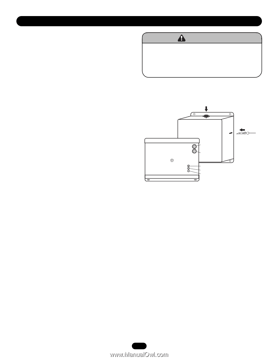
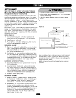
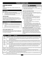
TESTING TEST PROCEDURES TO BE PERFORMED BY FACTORY AUTHORIZED PERSONNEL ONLY! CLEAR FIRE DOOR OPENING AND PROHIBIT TRAFFIC THROUGH DOOR OPENING WHILE TESTING! Testing does not affect normal operation of alarm system when connected to release device/control panel. Testing of the release device is independent of, and shall in no way be interpreted as an alternative method of, testing of a central fire alarm system, motorized operator and/or any other system component employed on the fire door or counter fire door installation. Complete testing and normal operation can only be accomplished with power applied to unit. Door must be in open position with power applied to unit to begin testing. The following procedures describe testing of all options. Verify options ordered and installed with unit. All tests may not apply. Refer to Figure 13 for location of all the LEDs and switches mentioned in this section. INITIAL POWER UP 1. Connect black battery wire to the black terminal on the battery. Connect the red battery wire to the red terminal. 2. Apply line power to the unit. 3. Power LED (red) and battery LED (green) will be lit on the bottom of the release device (Figure 13). MECHANICAL RELEASE 1. Depress and continue to hold test button on side of release device. Unit will beep as delay expires. After the selected delay expires, the device will release the end link and allow door to drop. Release test button. 2. Reset the door per door manufacturer's instructions. Raise door and then reset the release device by pushing downward on the mechanical reset button at the top of the device. Fully insert the end link through the side opening on the device and release the reset button in order to latch end link. CLOSE DOOR DETECTION (OPTIONAL) 1. Using the chain hoist or motor operator, lower the door to fully closed position. 2. Verify that Release Disabled LED (yellow) is lit indicating door closure. Depress and continue to hold test button on side of release device for 10 seconds. Close Door Detection logic will prohibit the release device from energizing and releasing the end link. Reset the test button (Figure 13). 3. Raise door to fully open position. WARNING To prevent possible SERIOUS INJURY or DEATH: CAUTION • Clear fire door opening and prohibit ALL traffic through door opening while testing. • Test every 90 days to assure proper operation of release device. FIGURE 13 Mechanical Reset Plunger AVERTISSEMENT Front of Release Device End Link Electronic ATTENTION Bottom of Release Device Reset Button Test Button Red LED (Line Power Present) Green LED (Battery Backup Power Present) Yellow LED (Release Disabled) After completing all tests, make sure the door is in it's normal position (open or closed) and all power required for normal operation is restored to unit. The release device is designed to operate with power applied. NOTE: Testing shall be performed and witnessed for proper operation. ADVERTENCIA PRECAUCIÓN SUSPENSION OF POWER 1. Make sure door is in fully open position. Turn off all power to release device and disconnect battery. Immediately upon loss of power (line voltage and battery backup) to the release device, a mechanical release will be initiated. 2. Reset the door per door manufacturer's instructions. Raise the door and then reset the release device by pushing downward on the Mechanical Reset Plunger at the top of the device. Fully insert the end link through the side opening on the device and release the Mechanical Reset Plunger in order to latch end link. Press the "Reset" button on the device to reset the alarm loop. 11
-
 1
1 -
2
-
3
-
4
-
5
-
 6
6 -
 7
7 -
 8
8 -
 9
9 -
 10
10 -
 11
11 -
 12
12 -
 13
13 -
 14
14 -
 15
15 -
 16
16
 |
 |