LiftMaster LM21XPBB LM21XPBB Manual - Page 5
Wiring
 |
View all LiftMaster LM21XPBB manuals
Add to My Manuals
Save this manual to your list of manuals |
Page 5 highlights
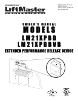
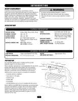
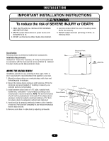
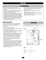
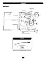
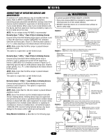
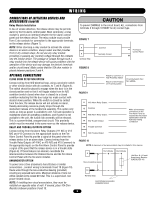
ING WWI RAIRNNGING ON WARNING To reduce the risk of SEVERE INJURY or DEATH: • ALL power wiring should be on a dedicated circuit and well • ALL electrical connections MUST be made by a qualified protected. The location of the power disconnect should be individual. visible and clearly labeled. • Disconnect power at the fuse box BEFORE proceeding. Release • ALL power and control wiring MUST be run in separate device MUST be properly grounded and connected in conduit. accordance with local electrical codes. • 120Vac should ONLY be attached to the 3-position terminal • Installation of ALL wiring and connections, including Class 1 block mounted within the enclosure. and Class 2 circuits, shall be performed in accordance with, • DO NOT disconnect battery or remove battery fuse while unit but not limited to, the latest NFPA, UL and N.E.C. standards is under power, the door will drop. and codes. In addition, ALL installations subject to Canadian standards shall be performed in accordance with the Canadian Electrical Code, Part I, with respect to wiring material type, SEMENT AVERTISSEMENT wiring gauge related to power capacity requirements and circuit length and wiring methods. WARNING ON WIRING INSTRUCTIONS Verify wiring configuration with that recommended by AVERTISSEMENT door CAUTION manufacturer for use of this product with specific door and To prevent DAMAGE to the circuit board, ALL connections from accessories being utilized. The use of 18 AWG wire is terminals 3 through 16 MUST be dry contact type. recommended. 1. Close fire door prior to ANY wiring. 2. Turn off power supply sources for the release device as well as the door operator, before beginning. FIGURE 1 Mechanical Reset Plunger 3. Verify voltage rating of release device to power source being utilized. Voltage is indicated on the side of the unit. Verify that power is disconnected before proceeding. 4. When powering the device from 120Vac line voltage, locate the 3-position terminal block mounted within the device enclosure. Connect 120Vac (single phase) power source inputs to terminals L1 (line) and L2 (neutral) of the terminal block (Figure 1). The third position is used for earth ground. Power Strip Ground L2 L1 AVERTISSEMENT ENCIA ADVERTENCIA ATTENTION 5. When powering the device from 24Vac or 24Vdc power, connect to terminal board positions 1 and 2 (Figure 2). Observe proper polarity. CIÓN ADVERTENCIA 6. Do not connect line power or battery until all field wiring is complete per the following pages. The battery provides backup power in the event of a loss of line voltage and prevents the release of the fusible link assembly and the resulting door closure. A pulsing sounder occurs when the battery is disconnected or when replacement is required. The battery also provides power to the various ancillary devices (i.e., smoke detectors, horn/strobes, etc.). FIGURE 2 Option DIP Switch + 1 2- 24Vac or 24Vdc ADVERTENCIA 5 PRECAUCIÓN
-
 1
1 -
 2
2 -
 3
3 -
 4
4 -
 5
5 -
 6
6 -
 7
7 -
 8
8 -
 9
9 -
 10
10 -
 11
11 -
12
-
13
-
14
-
15
-
16
 |
 |