LiftMaster LM21XPBB LM21XPBB Manual - Page 12
Troubleshooting
 |
View all LiftMaster LM21XPBB manuals
Add to My Manuals
Save this manual to your list of manuals |
Page 12 highlights
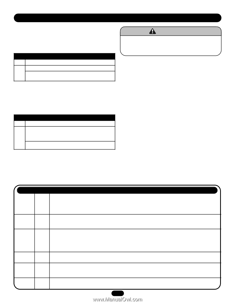
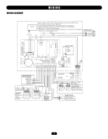
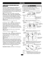
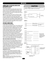
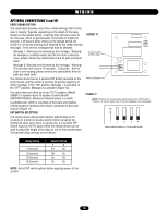
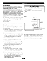
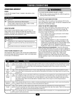
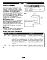
TROUBLESHOOTING OPERATIONAL CHECKLIST POWER Is the red LED, labeled "Power," located on the bottom of the enclosure lit? Is the Red LED Lit? Yes Move on. No Check power connections per Wiring Diagram. Check voltage; voltage should be 120Vac, 24Vac or 24Vdc connected as part of the wiring diagram. CHECK THE ALARM Are the alarm (smoke detection) inputs correct? If not, the release device will not release the fusible link assembly in a fire condition. Conversely, the release device will always release the fusible link assembly when powered or reset. Are the Alarm Inputs correct? Yes Move on. No Check that it is a dry contact input. There should not be any voltage on the alarm lines when they are disconnected from the unit. Verify that all wiring is per manufacturers' instructions. CIRCUIT BOARD DIAGNOSTIC LEDS View diagnostic LEDs present on the circuit board located behind the terminal block (See Wiring Diagram). Refer to the table below for the status LED indications. WARNING To prevent possible SERIOUS INJURY or DEATH: CAUTION • Clear fire door opening and prohibit ALL traffic through door opening while trouble shooting. CHECK THE CLOSE DOOR DETECTION Is the Yellow LED on the bottom of the enclosure lit? If lit, the close limit detection input is active, the devise is disabled and will not perform a mechanical release. CHECK THE BATTERY CONNECTIONS Is the Green LED on the bottom of the enclosure lit? If so, the battery is connected properly. If the LED does not light, the battery is not functioning properly and a trouble sounder will annunciate. Check the following: AVERTISSEMENT 1. Are the battery leads properly connected or do the leads have a defective connector? 2. Do the battery connections observe correct polarity - Red (+) and Black (-)? ATTENTION 3. Is the battery discharged? If so, allow 10 minutes for the battery management system to recharge the battery. If the sounder does not stop after this time, then the battery needs to be replaced. Refer to the "Replacement Parts and Accessories" section of this manual for ordering instructions. Battery Performance Inconsistencies - Does the unit go into alarm and release the fusible link as soon as power is applied? If so, then check the wiring and connections on the smoke detector loop, focusing especially on the presence and the correct placement of the end-of-line resistor. Also, if N/O smoke detectors are being used, make certain that the Wire Jumper between positions 5 and 6 on the release device's terminal strip is in place. LED LED Color Description N/O Detector Trouble Yellow (LED 6) If lit, indicates a trouble condition (open) within the N/O 2-wire (or 4-wire) smoke detector loop (emanating from terminal board positions 3 and 4), resulting from either incorrect wiring or incorrect placement of the end-of-line resistor, and the ADVERTENCIA smoke detector loop is inactive. Refer to the Smoke Detector Installation section of this manual for correct wiring instructions (Figures 3-5). N/O Detector Alarm N/C Detector Trouble Close Door Detection Red If lit, indicates that the N/O 2-wire (or 4-wire) smoke detector loop (emanating from terminal board positions 3 and 4) PRECAUCIÓN (LED 5) is in alarm. When lit during testing, press the Auxiliary Reset Button at the bottom of the release device to reset the loop (Figures 3-5). Red (LED 4) If lit, indicates an open circuit within the N/C 4-wire smoke detector loop (emanating from terminal board positions 5 and 6), resulting from either incorrect wiring or incorrect placement of the end-of-line relay or the detector(s) are in alarm. If in alarm, cycle power off and then on to the smoke detectors to reset, then depress the auxiliary reset button to reset the release device. Refer to the Smoke Detector Installation section of this manual for correct wiring instructions (Figures 6 and 7). Green If lit, indicates that the fire door or shutter is closed and activating the proximity switch. If not lit, refer to the Close Door (LED 2) Detection section of this manual for correct wiring instructions (Figure 8). Annunciator Yellow If lit, indicates a trouble condition (open) within the annunciator loop (emanating from terminal board positions Trouble (LED 9) 9 and 10), resulting from either incorrect wiring or incorrect placement of the end-of-line resistor. Refer to the Annunciator section of this manual for correct wiring instructions (Figure 10). Ground Fault Yellow If lit, indicates that one of the ancillary devices/loops (smoke detector, annunciator, etc.) is not grounded properly, and a (LED 3) short to earth ground exists. 12
-
 1
1 -
2
-
3
-
4
-
5
-
6
-
 7
7 -
 8
8 -
 9
9 -
 10
10 -
 11
11 -
 12
12 -
 13
13 -
 14
14 -
 15
15 -
 16
16
 |
 |