LiftMaster LM21XPBB LM21XPBB Manual - Page 8
Normally Open 2-Wire, Class B Style A Initiating Devices - door openers
 |
View all LiftMaster LM21XPBB manuals
Add to My Manuals
Save this manual to your list of manuals |
Page 8 highlights
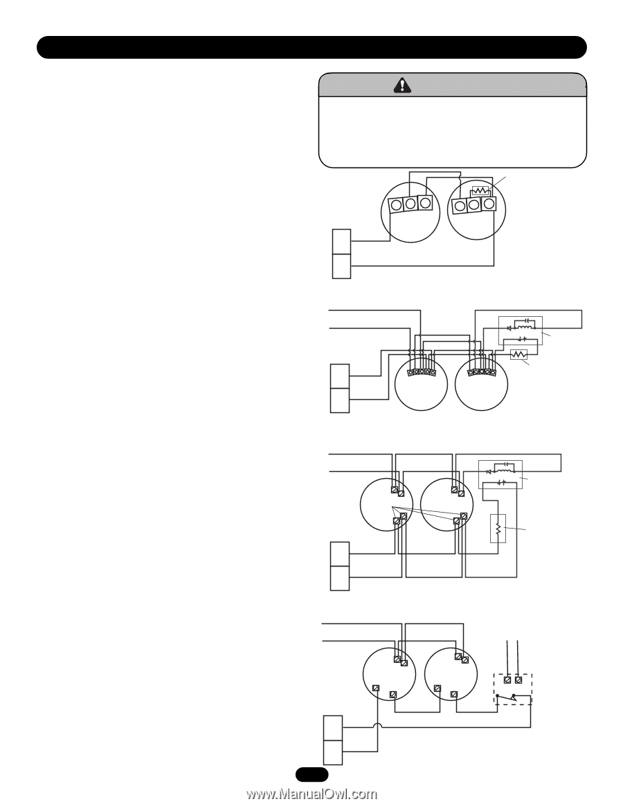
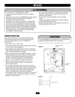
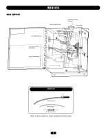
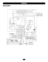
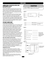
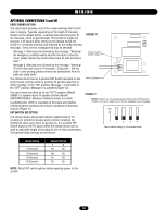
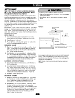
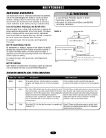
WIRING CONNECTIONS OF INITIATING DEVICES AND ACCESSORIES A maximum of 4 smoke detectors may be installed with this device. Refer to NFPA 72 and NFPA 80 for instructions concerning proper placement and detection coverage. End-of-line devices must be installed for supervision of electrical power to 4-wire smoke detector. When using 4-wire smoke detectors with this device, electrical supervision must be provided by means of a UL/ULC listed end-of-line relay. NOTE: For low voltage wiring #18 AWG is recommended. WARNING To prevent possible SERIOUS INJURY or DEATH: CAUTION • End-of-line devices MUST be installed for supervision of electrical power to 4-wire smoke detector. • DO NOT install this device on a motorized door without an electric safety edge. FIGURE 3 10k Ohm @1/2 watt Supervisory Resistor (LMEOLRES-10) Normally Open "2-Wire," Class B Style A Initiating Devices Connect wiring from N/O initiating device loop to positions 3 and 4. Place the supervisory resistor (LMEOLRES-10) contained within the accessory pack. (Figure 3). Observe proper polarity, 3 (+), 4 (-) when attaching to the release device's terminal board. NOTE: Make certain that the Wire Jumper is placed between positions 5 and 6. This option is a supervised, current-limited circuit. OR Normally Open "4-Wire," Class B Style A Initiating Devices Connect wiring from N/O 4-Wire initiating device loop to positions 3 and 4, making sure an end-of-line supervisory resistor (LMEOLRES-10) is installed as shown in Figure 4 or 5, depending upon the type of smoke detector being used. Observe proper polarity, 3 (+), 4 (-) when attaching to the release device's terminal board. NOTE: Make certain that the Wire Jumper is placed between positions 5 and 6. This option is a supervised, current-limited circuit. OR Normally Closed "4-Wire," Class B Style A Initiating Devices Connect wiring from N/C 4-Wire initiating device loop to positions 5 and 6 (Figure 6). This option is a supervised, current-limited circuit. NOTE: Make certain that the 10k ohm resistor is placed between positions 3 and 4. NOTE: End-of-line devices must be installed adjacent and after the last initiating device. Initiating device loops are supervised and cannot be direct series or paralleled between multiple release devices or shared with other alarm equipment. For proper wiring configurations from multiple smoke detectors or signaling for simultaneous closure on multiple doors, call technical support, 1-888-528-7870. Incorrect wiring between devices may cause damage to the release control circuit and void warranty. OR Relay Module Installation as described on the following page. - IN/OUT + OUT + IN - IN/OUT + OUT + IN 24Vdc Power from Terminal Strip 3 NOTE: Follow this method of attachment when using LM2W-B, LM2WT-B, or 4 other 2-wire 24Vdc smoke detectors. AVERTISSEMENT NOTE: Follow this method of attachment when using LM4W-B, FIGURE 4 LM4WT-B, or other N/O 4-wire smoke detectors. (-) Power from Control Panel (+) Terminal Strip ATTENTION LMEOLR1224 12/24 Vdc EOL Relay 10k Ohm @1/2 watt 3 Supervisory Resistor (LMEOLRES-10) COM NO - IN/OUT + OUT + IN COM NO - IN/OUT + OUT + IN 4 FIGURE 5 (+) NOTE: Follow this method of attachment when using LM4W-B, LM4WT-B, or other N/O 4-wire smoke detectors. Power from Control Panel (-) LMEOLR1224 (+) Alarm Contacts (-) (+) (-) 12/24 Vdc EOL Relay Style A (N/O) 10k Ohm @1/2 watt Terminal Strip Supervisory Resistor (LMEOLRES-10) (+) 3 ADVERTENCIA 4 PRECAUCIÓN (-) IMPORTANT: When using 4-wire smoke detectors with this device, the smoke detectors must be powered from a source other than the FIGURE 6 release device, such as an approved UL1481 regulated power supply providing battery backup support. (-) Power from Control Panel NOTE: Generic version of a N/C 4-wire smoke detector is shown. (+) Power from (+) (+) Control Panel (-) (-) N/C C N/C C (+) (-) LMEOLR1224 12/24 Vdc EOL Relay Terminal Strip Purple - 5 - IMPORTANT: When using 4-wire smoke detectors with this + 6 doethveicreth, athnethsme orekleeadseetedcetovricsem, suusct hbeaspoawnearpe-pdr+ofrvoemd a source UL1481 regulated power supply providing battery backup support. 8 +
-
 1
1 -
2
-
 3
3 -
 4
4 -
 5
5 -
 6
6 -
 7
7 -
 8
8 -
 9
9 -
 10
10 -
 11
11 -
 12
12 -
 13
13 -
14
-
15
-
16
 |
 |