LiftMaster LM21XPBB LM21XPBB Manual - Page 9
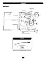
Caution
 |
View all LiftMaster LM21XPBB manuals
Add to My Manuals
Save this manual to your list of manuals |
Page 9 highlights
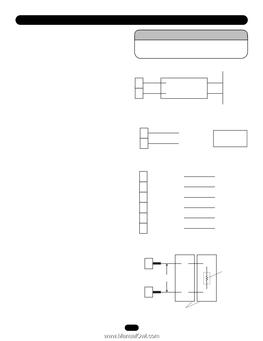
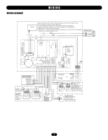
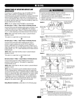
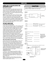
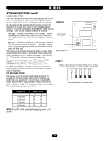
WIRING WARNING CONNECTIONS OF INITIATING DEVICES AND ACCESSORIES (cont'd) CAUTION Relay Module Installation In lieu of smoke detectors, the release device may be put into alarm by the fire alarm control panel. Most commonly, a relay module is used as an interface between the fire alarm control panel and the release device. The relay module must provide Form C dry contacts for connection to the appropriate terminals on the release device (Figure 7). To prevent DAMAGE to the circuit board, ALL connections from terminals 3 through 16 MUST be dry contact type. FIGURE 7 NOTE: When choosing a relay module to activate the release device in an alarm condition, always select one that provides Form C dry contact relays. Do not use any relay module providing or passing any (control) voltage through the contacts into the release device. The passage of voltage through such a relay module into the release device will cause problems with the operation of the device and may damage the device's terminals and/or circuit board. Make certain that the 10k ohm resistor is placed between positions 3 and 4. 5 6 Terminal Strip FIGURE 8 Common Normally Closed - Fire Alarm Control Panel + AVERTISSEMENT ATTENTION OPTIONAL CONNECTIONS CLOSE DOOR DETECTION OPTION Connect wiring from N/O electrical loop, using a proximity switch or other similar device with dry contacts, to 7 and 8 (Figure 8). The switch should be placed to engage when the door is in the closed position and so that it will toggle states from its N/O condition (switch closed when door is closed) to a closed condition indicating that the door edge has made contact with desired down position. When the switch is closed by contact from the door, the release device will not activate on alarm, thereby eliminating nuisance gravity drops through the inadvertent release of the fusible link assembly. This option only works as long as power is available to unit. Fail-safe operation is maintained under all operating conditions, and if power is not available to the unit, the fusible link assembly will be released. This is a power-limited, unsupervised circuit. This proximity switch must be mounted in the same room as the release device. RELAY AND TROUBLE OUTPUTS OPTION 7 8 FIGURE 9 Attach to Common on N/O Proximity Switch Attach to N/O Position on Proximity Switch Proximity Switch Part No. LM56A 11 N/C Alarm Relay Output 12 Common 13 N/O Alarm Relay Output 14 N/C Trouble Output Make all necessary connections to the Fire Alarm Panel as required by the project specifications and the Authority Having Jurisdiction ADVERTENCIA 15 Trouble Common Connect wiring from the Alarm Relay Outputs (#11 N/C or #13 N/O and #12 Common) to the appropriate inputs on the Fire Alarm Control Panel to provide a signal at the panel when the 16 N/O Trouble Output PRECAUCIÓN release device is in an alarm state. Connect wiring from the FIGURE 10 Trouble Relay Outputs (#14 N/C or #16 N/O and #15 Common) to the appropriate inputs on the Fire Alarm Control Panel to provide NOTE: A maximum of two annunciators may be installed in this manner. a signal at the panel that the release device is in a trouble state (Figure 9). If these features are desired, coordinate the interconnection between the Release Device and the Fire Alarm Control Panel with the fire alarm installer. ANNUNCIATOR OPTION To power one or two (maximum) horn/strobes or similar annunciators , connect wiring to terminals 9 and 10 (Figure 10). Horn/Strobe Horn/Strobe 9 + + + + Non-conductive sleeve + + 10k Ohm @ 1/2 watt Supervisory Resistor (LMEOLRES-10) Route wires through the non-conductive sleeving (provided) 10 - - covering any exposed bare wires. Maximum distance of wire run within conduit not to exceed 20' total. This is a supervised, non Terminal Strip - - power-limited circuit. NOTE: If installing two visual annunciators, they must be installed on opposite sides of wall. If unused, place 10k Ohm Horn/Strobe Annunciator #LMHS2475A-DA - Resistor between positions 9 and 10. 9
-
 1
1 -
2
-
3
-
 4
4 -
 5
5 -
 6
6 -
 7
7 -
 8
8 -
 9
9 -
 10
10 -
 11
11 -
 12
12 -
 13
13 -
 14
14 -
15
-
16
 |
 |