LiftMaster LM21XPBB LM21XPBB Manual - Page 2

Warning, Caution - parts

Page 2 highlights

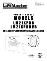
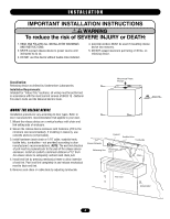
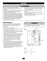
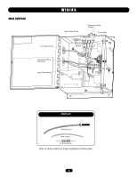
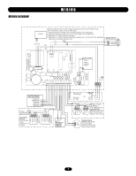
TABLE OF CONTENTS INTRODUCTION General Description 2 Agency Requirements 3 Specifications 3 WARNING Preparation 3 INSTALLATION Important Installation Warnings 4 CAUTION Mount the Release Device 4 WIRING Wiring Instructions 5 Wire Routing 6 Wiring Diagram 7 Connections of Initiating Devices and Accessories 8-9 Optional Connections 9-10 TESTING Test Procedures 11 TROUBLESHOOTING Operational Checklist 12 MAAVINETERNATNCISE SEMENT Maintenance Requirements 13 ATTENTION Enclosure Mounted LEDs Status Indicators 13 ACCESSORIES AND REPAIR PARTS 14 APPENDIX 15 WARNING Mechanical CAUTION WWEAlAecRRtriNcNaIlINNGG CAWUATRIONNING When you see these Safety Symbols and Signal Words on the following pages, they will alert you to the possibility of serious injury or death if you do not comply with the warnings that accompany them. The hazard may come from something mechanical or from electric shock. Read the warnings carefully. When you see this Signal Word on the following pages, it will AVERTISSEMENT alert you to the possibility of damage to your door and/or the door operator if you do not comply with the cautionary statements that accompany it. Read them carefully. AVAETRTETINSTSIEOMNENT IMPORTANT NOTAESV: ERTISSEMENT • BEFORE attempting to install, operate or maintain the release device, you must read and fully understand this manual and AAVTETRETNITSISOENMENT follow all safety instructions. • DO NOT attempt repair or service of your release device unless you are an Authorized Service Technician. INTRODUCTION GENERAL DESCRIPTION The LiftMaster® LM21XPBB and LM21XPBBVB Release Device is UL/ULC listed normally energized fail-safe device designed for use on rolling doors, single-slide and center-parting level and inclined track doors. All models are normally energized fail-safe ADVERTENCIA releasing devices incorporating state-of-the-art electronic control circuitry. The release devices respond to emergency conditions generated from an automatic initiating device and are used in conjunction with a fusible link system. PRECAUCIÓN The release device can be powered from 120Vac, 24 Vac, or 24Vdc. The 24Vdc cannot be sourced from a fire alarm control panel or UL1481 regulated power supply. The devices can be activated via a smoke detector or an alarm relay from the panel's ADVERTENCIA Form C dry contact relay. The release device features include a 10, 20, 30 or 60 second delay on alarm, closed door detection capabilities, Form C relay outputs for the transmission of alarm and trouble signals transmitted to the fire alarm control panel, an PARDEVCEARUTCEINÓCNIA audible trouble sounder, and diagnostic feedback LEDs. ADVERTENCIA The release device is provided with a battery management system that can provide 24Vdc power for up to four smoke detectors and two horn strobes, as well as provide battery backup for the ADVERTENCIA release device and accessories. As with all releasing device PRECAUCIÓN systems, maximum fire protection is provided when installed in accordance with factory specifications and used with a fusible link systems. 2

  • 1
  • 2
  • 3
  • 4
  • 5
  • 6
  • 7
  • 8
  • 9
  • 10
  • 11
  • 12
  • 13
  • 14
  • 15
  • 16

When you see these Safety Symbols and Signal Words on the
following pages, they will alert you to the possibility of
serious
injury
or
death
if you do not comply with the warnings that
accompany them. The hazard may come from something
mechanical or from electric shock. Read the warnings carefully.
When you see this Signal Word on the following pages, it will
alert you to the possibility of damage to your door and/or the
door operator if you do not comply with the cautionary
statements that accompany it. Read them carefully.
Mechanical
Electrical
TABLE OF CONTENTS
WARNING
WARNING
WARNING
WARNING
CAUTION
CAUTION
2
INTRODUCTION
General Description . . . . . . . . . . . . . . . . . . . . . . . . . . . . . . . . . . .2
Agency Requirements
. . . . . . . . . . . . . . . . . . . . . . . . . . . . . . . . .3
Specifications . . . . . . . . . . . . . . . . . . . . . . . . . . . . . . . . . . . . . . . .3
Preparation . . . . . . . . . . . . . . . . . . . . . . . . . . . . . . . . . . . . . . . . . .3
INSTALLATION
Important Installation Warnings . . . . . . . . . . . . . . . . . . . . . . . . . .4
Mount the Release Device . . . . . . . . . . . . . . . . . . . . . . . . . . . . . .4
WIRING
Wiring Instructions
. . . . . . . . . . . . . . . . . . . . . . . . . . . . . . . . . . .5
Wire Routing
. . . . . . . . . . . . . . . . . . . . . . . . . . . . . . . . . . . . . . . .6
Wiring Diagram
. . . . . . . . . . . . . . . . . . . . . . . . . . . . . . . . . . . . . .7
Connections of Initiating Devices and Accessories . . . . . . . . . .8-9
Optional Connections . . . . . . . . . . . . . . . . . . . . . . . . . . . . . . .9-10
TESTING
Test Procedures . . . . . . . . . . . . . . . . . . . . . . . . . . . . . . . . . . . . .11
TROUBLESHOOTING
Operational Checklist . . . . . . . . . . . . . . . . . . . . . . . . . . . . . . . . .12
MAINTENANCE
Maintenance Requirements . . . . . . . . . . . . . . . . . . . . . . . . . . . .13
Enclosure Mounted LEDs Status Indicators . . . . . . . . . . . . . . . .13
ACCESSORIES AND REPAIR PARTS
. . . . . . . . . . . . . . .14
APPENDIX
. . . . . . . . . . . . . . . . . . . . . . . . . . . . . . . . . . . . . . . .15
IMPORTANT NOTES:
• BEFORE attempting to install, operate or maintain the release
device, you must read and fully understand this manual and
follow all safety instructions.
• DO NOT attempt repair or service of your release device unless
you are an Authorized Service Technician.
GENERAL DESCRIPTION
The LiftMaster
®
LM21XPBB and LM21XPBBVB Release Device is
UL/ULC listed normally energized fail-safe device designed for
use on rolling doors, single-slide and center-parting level and
inclined track doors. All models are normally energized fail-safe
releasing devices incorporating state-of-the-art electronic control
circuitry. The release devices respond to emergency conditions
generated from an automatic initiating device and are used in
conjunction with a fusible link system.
The release device can be powered from 120Vac, 24 Vac, or
24Vdc. The 24Vdc cannot be sourced from a fire alarm control
panel or UL1481 regulated power supply. The devices can be
activated via a smoke detector or an alarm relay from the panel’s
Form C dry contact relay. The release device features include a
10, 20, 30 or 60 second delay on alarm, closed door detection
capabilities, Form C relay outputs for the transmission of alarm
and trouble signals transmitted to the fire alarm control panel, an
audible trouble sounder, and diagnostic feedback LEDs.
The release device is provided with a battery management system
that can provide 24Vdc power for up to four smoke detectors and
two horn strobes, as well as provide battery backup for the
release device and accessories. As with all releasing device
systems, maximum fire protection is provided when installed in
accordance with factory specifications and used with a fusible link
systems.
INTRODUCTION