LiftMaster LM21XPBB LM21XPBB Manual - Page 7
Wiring Diagram - model
 |
View all LiftMaster LM21XPBB manuals
Add to My Manuals
Save this manual to your list of manuals |
Page 7 highlights
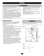
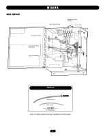
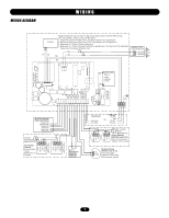
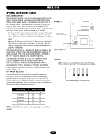
WIRING DIAGRAM WIRING Solenoid Replace batteries every 2 years. Field wiring shall consist of 22-18 AWG wiring. Use only 250Vac, 3 Amp, 3 AG, Slo-Blo fuses. 1. Supervised, power limited circuit, 20 Ohm maximum line impedance. 2. Unsupervised power limited circuit, 20 Ohm maximum line impedance. 3. Maximum of 4 Class B Style A detectors. 4. Maximum of 2 Class B Style W notification appliances. 0.5 Amp at 24 Vdc maximum. Supervised non-power limited circuit. Speaker- Voice board model only PU GY YE YE WH + Speaker - Speaker BK BK 12 V, 4.5 AHr Battery 2 Amp maximum current RD GR L3 L2 L1 3 Amp, 250 V, 3AG Slo-Blo Auxiliary Common Relay Connections Trouble NO Trouble Com Trouble NC Alarm NO Alarm Com Alarm NC 10 kOhm EOL Resistor (LMEOLRES10) Annunciator Loop (4) Place 10 kOhm resistor between 9 & 10 if unused + Strobe + Horn - Strobe - Horn + Strobe + Horn - Strobe - Horn N. O. Closed Door Proximity Switch (2) (optional) Input Power 120 Vac .5 Amp + 24V ac/dc OR Hot Neutral - 0.75 Amp Ground EOL 10 kOhm Resistor (LMEOLRES10) 2-Wire Detector Initiation Loop (1) (3) Place 10 kOhm resistor between 3 & 4 if unused + In + Out - In/Out + In + Out - In/Out NC COM Normally Closed Initiation Loop (1) (3) Place wire jumper between 5 & 6 if unused. External power required. 7
-
 1
1 -
 2
2 -
 3
3 -
 4
4 -
 5
5 -
 6
6 -
 7
7 -
 8
8 -
 9
9 -
 10
10 -
 11
11 -
 12
12 -
13
-
14
-
15
-
16
 |
 |
