LiftMaster LM21XPBB LM21XPBB Manual - Page 13
Maintenance - manual
 |
View all LiftMaster LM21XPBB manuals
Add to My Manuals
Save this manual to your list of manuals |
Page 13 highlights
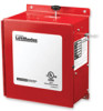
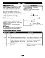
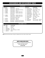
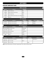
WARNING MAINTENANCE WARNING MAINCTENAAUNCTE IROEQNUIREMENTS The release device has no scheduled maintenance requirements. The unit has been designed and tested for use in dry, indoor locations. Testing of the unit at least once every 90 days is recommended, but test intervals shall ultimately be subject to criteria established by the Authority Having Jurisdiction (AHJ). FUSE REPLACEMENT PROCEDURE AND REPAIR PARTS One serviceable fuse, a 3 Amp, 3AG, slo-blo fuse, is required for proper operation and protection of the circuit board. The release device is shipped with the fuse in place and two replacement fuses are provided in a separate parts bag. The fuse is located on the circuit board near the battery cable connection. For replacement parts refer to Accessory and Replacement PAartsVpaEgeR. TISSEMENT BATTERY MAINTENANCE/TESTING No maintenance or testing is required for the battery. An audible ATTENTION warning tone, generated by the trouble annunciator mounted to the side of the release device, will sound when the battery is approaching the minimum operating threshold. This indicates the need to replace the battery. For replacement parts refer to Accessory and Replacement Parts page. BATTERY DISPOSAL Spent batteries must be treated as hazardous waste and disposed of in accordance with State, Local and Federal Regulations. WARNING To avoid SERIOUS PERSONAL INJURY or DEATH: • Stand clear of path of door. • Disconnect ALL electrical and battery power BEFORE performing maintenance. FIGURE 14 Mechanical Reset Plunger AVERTISSEMENT Front of Release Device End Link Electronic Reset Button AVERTISSEMENT Bottom of Release Device Test Button Red LED (Line Power Present) Green LED (Battery Backup Power Present) Yellow LED (Release Disabled) ENCLOSURE MOUNTED LEDS STATUS INDICATORS LED Label LED Color Description Action Required Battery Green If the Green LED is lit, then the battery is connected If the LED does not light, check that the leads are properly and charged above the minimum acceptable connected to the battery as shown on the wiring diagram. level. ADVERTENCIA ADVERTENCIA Disable Yellow The Yellow LED will light when the door reaches the close If the LED does not light when the door reaches the close limit and activates a proximity switch attached to terminal door detection and activates the proximity switch, then PRECAUCIÓN ADVERTENCIA positions 7 and 8 on the release device. This configuration check that the proximity switch has been activated and results in the device not releasing the fusible link that the switch is set to normally open (N.O.). Check to assembly in alarm or power loss situations and should make certain that the switch is attached to terminal only be used when the fire door is kept in a constant positions 7 and 8 on the release device. closed position. Power Red If the Red LED is lit, then the line power is connected and If the LED does not light when power is applied, check switched "on." that power is connected as described in the installation manual electrical connections. 13
-
 1
1 -
2
-
3
-
4
-
5
-
6
-
7
-
 8
8 -
 9
9 -
 10
10 -
 11
11 -
 12
12 -
 13
13 -
 14
14 -
 15
15 -
 16
16
 |
 |