LiftMaster LM21XPBB LM21XPBB Manual - Page 3
Warning
 |
View all LiftMaster LM21XPBB manuals
Add to My Manuals
Save this manual to your list of manuals |
Page 3 highlights
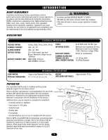
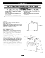
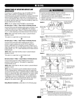
INTRODUCTION AGENCY REQUIREMENTS Installation and testing to factory specifications shall be performed by factory authorized personnel for proper operation in accordance with the latest National Fire Protection Association (NFPA), Underwriters Laboratories (UL), National Electrical Code (NEC), local, state, county, district and/or other applicable building and fire standards, guidelines, regulations and codes including, but not limited to, all appendices and amendments and the requirements of the local authority having jurisdiction (AHJ). WARNING To prevent possible SERIOUS INJURY or DEATH: CAUTION • DO NOT use this device without fusible links installed. • Test every 90 days to assure proper operation of release device. SPECIFICATIONS ELECTRICAL SPECIFICATIONS VOLTAGE RATING: STANDBY CURRENT ALARM CURRENT BATTERY RATING: BATTERY STANDBY TIME: 120Vac, 60Hz; 24Vac, 60Hz; 24Vdc .06A, .3A, .2A .06A, .3A, .25A 12V 4.5AH Sealed Lead Acid Battery, Maximum charge current .150Amps LM21XPBB, 72 Hours LM21XPBBVB, 24 Hours FUSES: 3A @ 250V, 2AG Slo-Blo Type INITIATING DEVICE: Maximum line impedance 20 ohm; AVERMTaxiImSumScEurrMent EnotNtoTexceed .010A.; Maximum voltage 24Vdc AUXILIARY POWER: 24Vdc @ .5A Maximum COMMON ALARM ANAD TTENTION TROUBLE RELAYS: .5A 125Vac 60Hz (MAX. CONTACT RATING) 1A 24Vdc Resistive LOAD RATING: PHYSICAL DIMENSIONS: MECHANICAL SPECIFICATIONS Support and Release 40 lbs. Max. 9.7" x 7.5" x 5" (h x w x d) WEIGHT: (INCLUDING BATTERIES) Approximately 18 lbs. PREPARATION It is imperative that the wall or mounting surface provide adequate support for the release device. Refer to the door manufacturer's recommendations for use of this Smoke Detector product with specific door being utilized. Use only hardware approved or recognized by the appropriate testing and listing agencies in conjunction with the installation of this product. Releasing Unit Additional items may be required to complete the installation: • Concrete anchors or fasteners • Sash chain or 1/16 cable • Eyebolts-hook • Fusible links • Turnbuckles • Smoke detectors (up to 4 may be installed with this device) Refer to NFPA 72 and NFPA 80 for instructions concerning proper placement and detection coverage. End-of-line devices shall be installed for supervision of electrical power to 4-wire smoke detector. When using 4-wire smoke detectors with this device, electrical supervision must be provided by means of a UL/ULC listed end-of-line relay. Eyebolt Fusible Links Turnbuckle ChaAin EDnd VERTENCIA Link Chain PRECAUCIÓN Fire Door Annunciator 3
-
 1
1 -
 2
2 -
 3
3 -
 4
4 -
 5
5 -
 6
6 -
 7
7 -
 8
8 -
 9
9 -
10
-
11
-
12
-
13
-
14
-
15
-
16
 |
 |