LiftMaster MEGA ARM / MEGA ARM TOWER MATDCBB Green Control Board V.6.4 or newe - Page 10
Timers And Mode Selections S1 & S2, Close Timer - Switch Pack S2 (1-5)
 |
View all LiftMaster MEGA ARM / MEGA ARM TOWER manuals
Add to My Manuals
Save this manual to your list of manuals |
Page 10 highlights
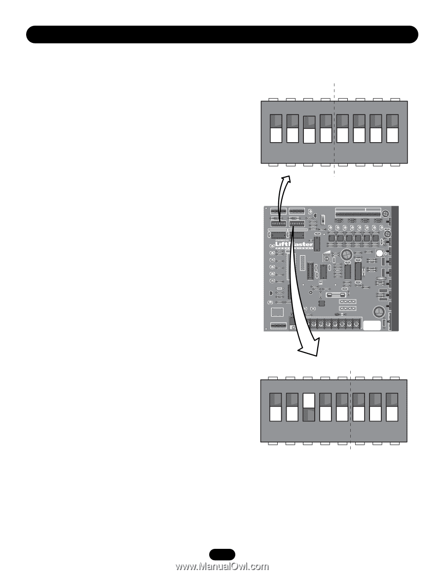
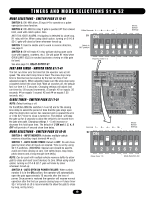
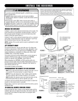
TIMERS AND MODE SELECTIONS S1 & S2 MODE SELECTIONS - SWITCH PACK S1 (5-8) SWITCH 5: ON -Will allow J5 input #4 to operate as a pulse open/pulse close function. SWITCH 6: ON -Will fire relay if gate is pushed UP from closed limit, used with clutch option. Also ANTI TAIL-GATE ALARM, if tailgating is detected by close loop, K1 relay will fire. When using clutch option, turning on S1-6 & S2-7, gate will close by timer whenever forced up. SWITCH 7: Used to enable arm to work in reverse direction, see page 9. SWITCH 8: Off will make K1 relay activate during open cycle (use with buzzers, counters, etc.). On will pulse K1 relay when OPEN LIMIT (OLS) is reached (activates a swing or slide gate its lane). See also page 18, RELAY OUTPUT-K1 FAST RUN TIMER - SWITCH PACK S1 (1-4) The fast run timer sets the time that the operator runs at full speed. The slow start ramp time is fixed. The slow stop ramp time is fixed but can be overrun by the fast run time if not adjusted properly. When adjusting make sure the slow stop ramp completes before the close limit. With all switches off, the default fast run time is 1.5 seconds. Changing settings will adjust fast run timer by 1/8 second increments. (Example: #2 on equals .25 seconds, #4 on equals 1 second. #2 and #4 on equals 1.25 seconds, etc.) CLOSE TIMER - SWITCH PACK S2 (1-5) NOTE: Default setting is off. On the MEGA ARM the switches 1-5 on S2 are for the closing time delay to select the period of time that the gate stays open after the obstruction sensor has reversed and re-opened the arm or if the S2-7 timer to close is turned on. The default will keep the gate up for 4 seconds to allow the vehicle to be moved from the gate arm path. Changing settings 1 - 5 will increase or decrease this hold open time. The default of 3 ON and 1, 2, 4, 5 OFF will provide a 4 second close time delay. MODE SELECTIONS - SWITCH PACK S2 (6-8) SWITCH 6 - INPUT MEMORY: Activates multiple vehicle memory at auxiliary input terminal #4 on J5. SWITCH 7 - AUTO CLOSE TIMER: Default is OFF. On will close gate by timer when all inputs are cleared. Time is set by using S2 1-5 switches. (WARNING: Special care should be used to avoid arm from closing on cars. Use safety loops, stop loops, photo beams and a long enough time delay.) NOTE: Can be used with multiple vehicle memory buffer to allow gate to close and reset count memory to zero. When using clutch option, turning on S1-6 & S2-7, gate will close by timer whenever forced up. SWITCH 8 - AUTO OPEN ON POWER FAILURE: When switch number 8 is in the ON position, the operator will automatically open the gate approximately 15 seconds after the loss of power. Once power is restored the operator will resume normal operation after the first car passes closing loop or if close timer S2-7 in turned on (it is recommended to allow the gate to close by loop, not by timer). 1/8ths Seconds 1 - - - - 2 - - - - 4 - -- - -8 S1 ON Shows Default Settings Switch in OFF position OFF OFF OFF OFF OFF OFF OFF OFF 12345678 Fast Run Timer 1-4 C18 U18 C15 Q6 Q5 Q4 D28 1 1 J2 AUX LIMITS M/S J3 R14 D8 D1Ø R18 S1 S2 1 2345678 1 2345678 R1 R12 R17 R16 MANUAL Q2 OPEN 1 2 3 4 5 6 7 8 9 1Ø 11 12 J5 S3 T2 T4 T6 T8 T1 T3 T5 T7 OPEN 1 OPEN 2 OPEN 3 AUX 4 SAFETY 5CLOSE 6 BACK 7SHADOW 8 CLOSE R21 C16 D24 D17 R36 D18 R42 D19 R47 D22 R53 D23 D16 D15 C3 R24 R35 R41 R46 R5Ø R61 R3Ø U4 U8 U9 U11 U13 U14 U15 C19 F5 C2 C 1 C2 U1 OLS D7 R23 R34 R4Ø R45 R49 R6Ø R22 R33 R39 R44 R48 R59 C22 OPEN X1 D6 R1Ø R9 BRAKE U6 IRD1 R26 R25 R43 R43 D21 R63 U16 R58 D5 R8 U5 C12 U12 D27 CLOSE D4 U7 DX3 C6 U1Ø DX4 X 2 C 7 R7 D29 CLS D3 R6 R57 C13 R56 IRD D2 U3 R5 U2 R4 C4 CPU R19 JP2 F2 R38 R37 R51 D2Ø DX2 R55 R3 Q1 D9 R2Ø + C5 F1 1A DC C8 C2Ø + R15 D1 + F4 R2 R11 B1 HBEAT BAT LO AC POWER K1 D11 D12 D14 F3 WARNING FOR R62 CONTINUOUS PROTECTION AGAINST FIRE DX1 REPLACE ONLY WITH THE SAME TYPE AND RATING OF FUSE D26 D25 - R13 U19 J4 BAT- MOV MOTOR Aux Relay TR J1 C NC NO DC 1 1 B2 + PWR ACC+ ACC- BAT- BAT+ 24VAC XFMR MOTOR Seconds 1 - - 2 - - 4 - - 8 - - 16 Shows Default Settings S2 ON ON OFF OFF OFF OFF OFF OFF OFF 12345678 Close Timer 1-5 Mode Selection 6-8 10
-
 1
1 -
2
-
3
-
4
-
 5
5 -
 6
6 -
 7
7 -
 8
8 -
 9
9 -
 10
10 -
 11
11 -
 12
12 -
 13
13 -
 14
14 -
 15
15 -
16
-
17
-
18
-
19
-
20
-
21
-
22
-
23
-
24
 |
 |