LiftMaster MEGA ARM / MEGA ARM TOWER MATDCBB Green Control Board V.6.4 or newe - Page 12
ADJUSTMENTS, OPERATION AND MAINTENANCE, To reduce the risk of SEVERE INJURY or DEATH
 |
View all LiftMaster MEGA ARM / MEGA ARM TOWER manuals
Add to My Manuals
Save this manual to your list of manuals |
Page 12 highlights
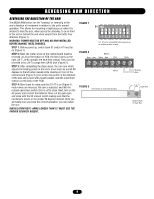
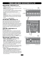
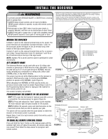
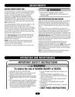
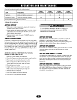
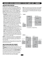
ADJUSTMENTS INSTANT REVERSE DEVICE (IRD) The reverse device is an internal circuit that continuously WARNING monitors the motors current for increased draw. Turning To reduce the risk of SERIOUS INJURY or DEATH: the IRD1 right (CW more sensitive), or left (CCW less sensitive) in small increments will allow sensitivity CAUTION • Disconnect power BEFORE performing ANY adjustments near drive shaft. adjustments (IF ARM DOES NOT REVERSE, DO NOT CONTINUE TO FORCE). The obstruction that you apply should STOP the arm. Adjust sensitivity so that consistent GATE ARM INSTALLATION AND LEVELING reversal occurs. If the gate stops while opening then the Install arm in gate arm bracket by lining up holes in arm with the IRD is TOO sensitive. slotted holes in bracket. Insert the bolts through the arm and Some slight adjustment either way may be needed so that the gate only reverses when obstructed. If gate is obstructed while closing, the gate will reverse to the open through the bracket. Next install the flat washers then the nylon nuts. (It is recommended the only nylon nuts be used to attach arms). position, time out (using the time delay set at S-2 switches The magnetic limit cam is pre-adjusted for near proper arm 1-5) and then close. If gate is opening when obstructed, travel, however if leveling of the arm is required this can be done gate will stop its open travel, then will time out and close through adjustment to the magnetic cam arm. Note that limit using the same delay set at S-2. range can be impacted from 85 to 89 degrees by sliding the main If S-2 switch number 8 is off (you have programmed the unit to NOT AUTO RAISE when power fails), then recheck AVERTISSEMENT board up and down in its slot. Always adjust for a level arm in the HORIZONTAL POSITION. There is a small set screw in the side of your adjustments with AC power off to be sure proper the cam arm which can be loosened to allow the cam arm magnet operation will be maintained. NOTES: Instant reverse device (IRD) should be tested to reach the close limit sensor (located on back of controller, H2) earlier or later in itsAtraTveTl. ENTION monthly to insure proper operation. If adjustments are Continue to open and close the gate while adjusting until a WARNING required, refer to above paragraph. Adjustments to be done by qualified service persons only. satisfactory horizontal stopping point can be maintained. Afterwards re-secure set screw in cam arm. NOTE: In some cases additional adjustments may be required after the belt wears in. When stopping in the open position, the arm will stop just before the full vertical position. NOTE: To prevent entrapment, allow for two (2) feet minimum clearance past end of arm when in down position. WARNING OPERATION AND MAINTENANCE IMPORTANT SAFETY INSTRUCTIONS WARNING ADVERTENCIA To reduce the risk of SEVERE INJURY or DEATH: 1. READ AND FOLLOW ALL INSTRUCTIONS. 2. NEVER let children operate or play with gate controls. Keep the remote control away from children. 3. ALWAYS keep people and objects away from the gate. NO ONE SHOULD CROSS THE PATH OF THE MOVING GATE. 4. Test the gate operator monthly. The gate MUST reverse on contact with a rigid object or stop when an object activates the non-contact sensors. After adjusting the force or the limit of travel, retest the gate operator. Failure to adjust and retest the gate operator properly can increase the risk of INJURY or DEATH. PRECAUCIÓN 5. Use the emergency release ONLY when the gate is not moving. 6. KEEP GATES PROPERLY MAINTAINED. Read the owner's manual. Have a qualified service person make repairs to gate hardware. 7. The entrance is for vehicles ONLY. Pedestrians MUST use separate entrance. 8. Disconnect ALL power BEFORE performing ANY maintenance. 9. ALL maintenance MUST be performed by a LiftMaster professional. 10. SAVE THESE INSTRUCTIONS. 12
-
 1
1 -
2
-
3
-
4
-
5
-
6
-
 7
7 -
 8
8 -
 9
9 -
 10
10 -
 11
11 -
 12
12 -
 13
13 -
 14
14 -
 15
15 -
 16
16 -
 17
17 -
18
-
19
-
20
-
21
-
22
-
23
-
24
 |
 |