LiftMaster MEGA ARM / MEGA ARM TOWER MATDCBB Green Control Board V.6.4 or newe - Page 16
Trap Instructions, Install The K1 Auxiliary Relay And Connector At
 |
View all LiftMaster MEGA ARM / MEGA ARM TOWER manuals
Add to My Manuals
Save this manual to your list of manuals |
Page 16 highlights
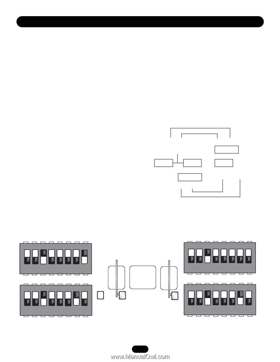
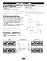
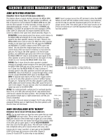
TRAP INSTRUCTIONS INSTALL THE K1 AUXILIARY RELAY AND CONNECTOR AT MEGA ARM CONNECTED TO THE ACCESS DEVICE 1. Press the relay into the K1 location ensuring the pins are properly aligned. 2. Press the connector into the J1 connector pins. INSTALL THE K1 AUXILIARY RELAY AND CONNECTOR AT THE SECOND 1. Press the relay into the K1 location ensuring the pins are properly aligned. 2. Press the connector into the J1 connector pins. WIRE THE CONNECTIONS BETWEEN THE OPERATORS 1. Connect the Normally open output (NO) of the K1 relay on the trap unit to the OPEN input (J5 - term#2) of the second unit. 2. Connect the common output (C) of the K1 relay of the trap unit to the common of the second unit (J5 - term#12). 3. Connect the Normally open output (NO) of the K1 relay on the second unit to the INTERLOCK input of the trap unit (J5 - term#8). 4. Connect the common output (C) (J5 - term#12) of the second unit to the common of the trap unit (J5 - term#12). SET THE DIP SWITCHES AT THE TRAP OPERATOR 1. Set switch bank S1 to 00100001 where 1 is up and 0 is down. 2. Set switch bank S2 to 00100010 where 1 is up and 0 is down. SET THE DIP SWITCHES AT THE SECOND OPERATOR 1. Set switch bank S1 to 00100000 where 1 is up and 0 is down. 2. Set switch bank S2 to 00100010 where 1 is up and 0 is down. RECONNECT THE POWER AND TEST 1. Reconnect the DC power by replacing the neutral (Black) wire to the battery terminal. 2. Reconnect the AC Power to the operator. 3. To test, activate the following sequence of inputs: a. Open the trap gate using the access device. b. When the trap gate is open, activate the close loop on the trap operator. The trap gate will close and the second gate should open. c. When the second gate is open, activate the close loop on the second operator. The second gate should close. TRAP SET UP Interlock C OPEN Trap TES MA S1-6 OFF S1-8 ON C NC NO DC C NC NO DC K1 S1-6 OFF S1-8 OFF MA Opener Common S1 Trap Operator ON ON ON ON ON ON ON OFF OFF 12345678 S2 ON ON ON ON ON ON ON OFF OFF 12345678 TRAP CONFIGURATION Must use trap kit. See Mega Arm Options Parts List S1 Mega ARM Operator ON Close Loop Trap Close Loop Close Loop ON ON ON ON ON ON ON OFF 12345678 Close Loop Trap S2 Card Reader Tele-entry Radio Control Mega Arm Trap Mega Arm ON ON ON ON ON ON ON OFF OFF 12345678 16
-
 1
1 -
2
-
3
-
4
-
5
-
6
-
7
-
8
-
9
-
10
-
 11
11 -
 12
12 -
 13
13 -
 14
14 -
 15
15 -
 16
16 -
 17
17 -
 18
18 -
 19
19 -
 20
20 -
 21
21 -
22
-
23
-
24
 |
 |