LiftMaster MEGA ARM / MEGA ARM TOWER MATDCBB Green Control Board V.6.4 or newe - Page 15
Suggested Loop Sensor Locations, Free Exit On Vehicle Approach, Entry With Access Control Device
 |
View all LiftMaster MEGA ARM / MEGA ARM TOWER manuals
Add to My Manuals
Save this manual to your list of manuals |
Page 15 highlights
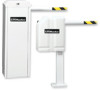
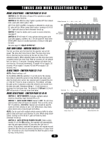
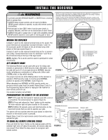
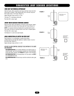
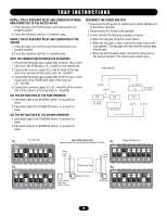
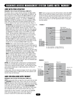
SUGGESTED LOOP SENSOR LOCATIONS FREE EXIT ON VEHICLE APPROACH Gate will open when sensed by exit loop and then close once the close loop is cleared. If the vehicle pulls up to the exit loop and then backs away, it will close (Figure 1). Space between loops will be 4' to 10'. Terminal #7 is backaway (free exit). Terminal #6 is close input. FIGURE 1 Close Loop Back Away Loop (Free Exit) ENTRY WITH ACCESS CONTROL DEVICE Gate will open when activated by an access control device. When vehicle passes and clears close loop, gate will close (Figure 2). NOTE: If a second vehicle tail-gates and is sensed at the close loop, gate will stop its closing motion until loop is cleared again. Terminal #6 is close input. Terminals #1, 2, and 3 are open inputs. DUAL DIRECTION AS ENTRY OR FREE EXIT Dual direction is a combination of both of the above configurations to provide the ability for traffic to enter or exit in the same lane (Figure 3). Space between loops will be 4' to 10'. FIGURE 2 Mega Arm Close Loop Mega Arm Card Reader Tele-entry Radio Control DO NOT ALLOW CONTROL DEVICES TO BE WITHIN 10' OF GATE OR OPERATOR RECOMMENDATION 1: If vehicle detectors are used to open or close the gate, use of the presence contacts are recommended. Using the pulse contacts will REDUCE the gate's safe operation. RECOMMENDATION 2: If closing timer is to be used, use ONLY on a dedicated free exit. RECOMMENDATION 3: Close loop must be centered under gate arm. Back Away Loop (Free Exit) FIGURE 3 Close Loop Card Reader Tele-entry Radio Control Mega Arm 15
-
 1
1 -
2
-
3
-
4
-
5
-
6
-
7
-
8
-
9
-
 10
10 -
 11
11 -
 12
12 -
 13
13 -
 14
14 -
 15
15 -
 16
16 -
 17
17 -
 18
18 -
 19
19 -
 20
20 -
21
-
22
-
23
-
24
 |
 |