LiftMaster MEGA ARM / MEGA ARM TOWER MATDCBB Green Control Board V.6.4 or newe - Page 17
Sequence Access Management System (sams) With “memory”, Sams Two Mega Arms With “memory”
 |
View all LiftMaster MEGA ARM / MEGA ARM TOWER manuals
Add to My Manuals
Save this manual to your list of manuals |
Page 17 highlights
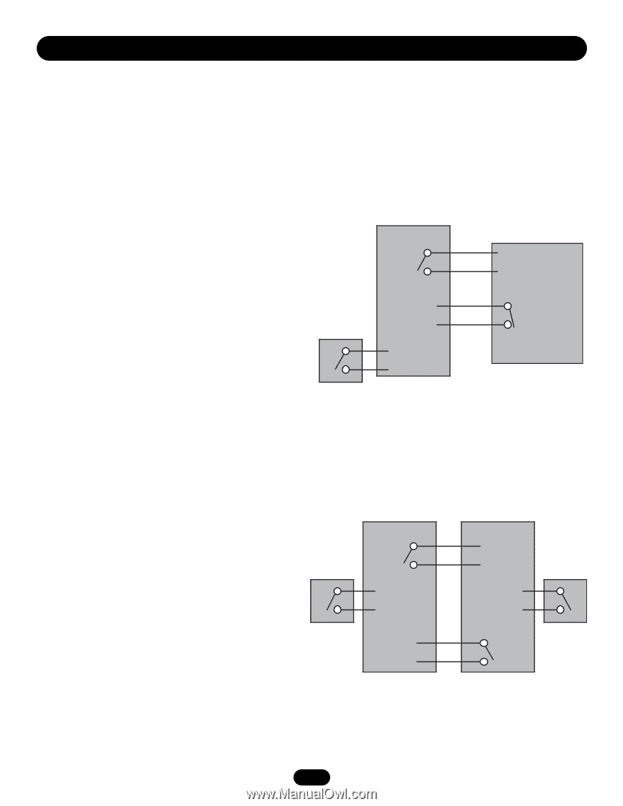
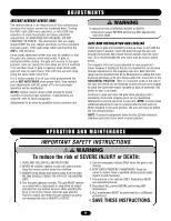
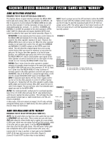
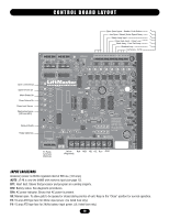
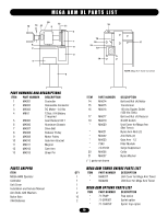
SEQUENCE ACCESS MANAGEMENT SYSTEM (SAMS) WITH "MEMORY" SAMS WITH OTHER OPERATORS REQUIRES THE K1 RELAY OPTION (Order SAMS KIT) This feature allows a logical interface between the MEGA ARM barrier gate and a swing, slide, etc. gate operator (or MTC-31). All that is required is 4 wires between the MEGA ARM barrier gate and the other operator. It will be necessary to have one set of dedicated/isolated dry contacts - {C. and N.C.} COMMON and NORMALLY CLOSED be available at the other operator's OPEN LIMIT SWITCH. Most units will require that this EXTRA limit switch be added to their open limit switch assembly (Figure 1). NOTE: Insert a jumper across the JP2 terminal to allow the SAMS feature to work with the multiple vehicle memory count selection, use the K1 relay to open the sequenced gate (S1-5 off, S2-6 on, jumper across JP2). This allows gate to store input counts via J5 #4 but not raise the arm until the sequenced slide or swing gate has fully opened. OPERATION: A one second pulse from access control device to the MEGA ARM will energize its K1 relay sending an open signal to the other operator causing it to open. However, the MEGA ARM's boom will not raise yet. When the other operator reaches its full open limit switch, this will open the COMMON and NORMALLY CLOSED contact on the EXTRA open limit switch. This will allow the original signal from your access control device (that was stored in memory) to now raise the gate arm. As long as the other operator is in the full open position, any additional open pulse sent will in turn energize the MEGA ARM's K1 relay to send another open signal to the other operator as well as cause the arm to raise again if it has closed via a car crossing the MEGA ARM's close loop. FIGURE 1 Access Device K1 Relay C NO J5 #11 J5 #8 Other Operator (Slide, Swing, Teeth, etc.) Open Input C Extra Open Limit Switch NC WIRING: Run 2 wires from the other operator's isolated common & normally closed contacts of its open limit switch to the MEGA ARM J5#8 and one of the commons J5, #9-12. Next, run 2 wires from the MEGA ARM's K1 relay (common & S1, #6 and #8 (ON) = K1 Relay PULSE only. S1, #6 and #8 (OFF) = K1 Relay LATCH only. normally open) to the other operators common and open input. (WARNING: max of 30 VOLTS at .5 amps through relay). J5 #8 was the unused SHADOW LOOP input on the MEGA ARM. NOTE: A separate open device (24 hour timer, toggle switch) can be run to the other operator to control it without raising the gate arm. Tampering with the other operator's safety loops, safety edges and reverse sensors WILL NOT cause the arm to raise if one tripped. The arm will only raise if an intended open signal was sent to the MEGA ARM. FIGURE 2 NOTES: For motorized teeth, vertical pivot or overhead operator, Mega Arm Mega Arm leave S1-6, S1-8 OFF (this will keep the K1 relay latched down until the arm reaches the down position. This will keep the other gate operator locked open or teeth locked down until the arm Visitor Lane K1 Relay C J5 #11 closes completely). Tele-Entry NO J5 #8 In this mode, if the arm senses an impact, the K1 relay will stay energized holding open (or teeth down) the other operator until J5 #1 J5 #1 the arm times out and closes. J5 #9 J5 #9 Resident Lane Reader, etc. SAMS TWO MEGA ARMS WITH "MEMORY" REQUIRES THE K1 RELAY OPTION (Order SAMS KIT) NOTE: Can be used when you have two entry gates that you want to SEQUENCE with each other. This is when you can only have ONE gate raised at a time (bottle neck or gates at a cross street). In this case, which ever one raises first will get first priority, while if the other gets an open signal, it will be HELD IN MEMORY, then raise once the first gate closes. This will work if either gate has a telephone entry unit or access device (AVI, prox, etc.). Connect the K1 relay C and N.O. of each gate to the SHADOW LOOP J5 #8 input and common of the other (Figure 2). (Leave S1-6 and 8 OFF to allow relay to stay latched.) 17 J5 #11 J5 #8 K1 Relay C NO
-
 1
1 -
2
-
3
-
4
-
5
-
6
-
7
-
8
-
9
-
10
-
11
-
 12
12 -
 13
13 -
 14
14 -
 15
15 -
 16
16 -
 17
17 -
 18
18 -
 19
19 -
 20
20 -
 21
21 -
 22
22 -
23
-
24
 |
 |