LiftMaster MEGA ARM / MEGA ARM TOWER MATDCBB Green Control Board V.6.4 or newe - Page 7
Wiring And Hookup, Input Commands Connections - mega arm
 |
View all LiftMaster MEGA ARM / MEGA ARM TOWER manuals
Add to My Manuals
Save this manual to your list of manuals |
Page 7 highlights
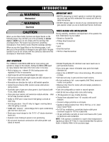
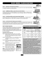
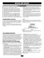
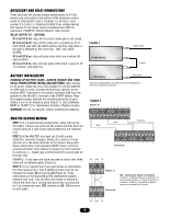
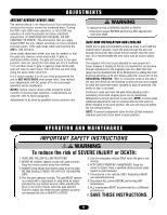
NG W I R I N WG AARNNDINHGO O K U P WARNING To reduce the risk of SEVERE INJURY or DEATH: • DO NOT install any wiring or attempt to run the operator • ANY maintenance to the operator or in the area near the operator MUST not be performed until disconnecting the electrical power and locking-out the power via the operator without consulting the wiring diagram. We recommend that you Install an optional reversing edge BEFORE proceeding with the control station installation. power switch. Upon completion of maintenance the area • ALL power wiring should be on a dedicated circuit and well MUST be cleared and secured, at that time the unit may be protected. The location of the power disconnect should be returned to service. visible and clearly labeled. • Disconnecting power at the fuse box BEFORE proceeding. • ALL power and control wiring MUST be run in separate conduit. Operator MUST be properly grounded and connected in accordance with local electrical codes. NOTE: The operator should be on a separate fused line of adequate capacity. • BEFORE installing power wiring or control stations be sure to follow all specifications and warnings described below. Failure to do so may result in SEVERE INJURY to persons and/or • ALL electrical connections MUST be made by a qualified individual. damage to operator. MENT AVERTISSEMENT AC POWER HOOKUP (120/230 Vac) 120 Vac N AVERTISSEMENT Be sure your main power is OFF before attempting to hook up the Connect the BLACK wire to the incoming 120 Vac hot lead and AC power. The AC wiring should be attached to the wires exiting connect the WHITE wire to the incoming neutral lead. Connect the the conduit or pedestal post. Only use U.L. approved 14AWG (or GREEN wire to the ground. larger) 600 volt insulated wire. Black NOTE: Do not connect any of the AC power wires directly to the electronic control board. Connect the batteries after the AC power is restored. Green White Neutral 120Vac Ground Pedestal Version Top End of 4"x4" Tube 230 Vac 120 Vac Please purchase the 120 to 230 Vac conversion kit for 230 Vac operation. See Accessory page. INPUT COMMANDS CONNECTIONS Use common and normally open contacts from devices connected 6, CLOSE: When used with a vehicle detector, it is to these inputs. Control wire connections at low voltage terminal recommended that the presence contacts (N.O. & C.) be used strip will be at the top of the electronic control board. Make for the close input. This input will close gate after input is NCIA ADVERTENCIA connections to the appropriate points for the desired operation, see applied and then removed. It will stop the open cycle and Control Board Layout page 18. Wires should be UL approved 600 reverse gate to close. (Example: Car crosses over close loop volt rated and at least 18 AWG. They are to be routed through the before arm reaches full open position- gate will reverse and ÓN ADVERTENCIA upper grommet in chassis to avoid chafing. All external control devices must have normally open dry contacts. close). (NOTE: The close input also acts as a safety-stop in that if gate is closing and a tailgater is sensed at the close input, the CAUTION: DO NOT CONNECT ANY DEVICE WHICH WOULD gate WILL STOP its closing motion and not continue to close DELIVER ANY VOLTAGE OF ANY KIND TO THESE TERMINALS. until the close input is removed or gate is re-opened). Terminals 9, 10, 11, 12 are the commons (0 Vdc) used to activate the following inputs: 1, 2, 3 OPEN: These inputs will trigger gate open when pulsed or hold gate open with maintained contact. When released gate will close if closing timer is on or if close input is given. 4, AUXILIARY OPEN: Same as 1, 2 and 3 with S2 switch 6 off. With S2 switch 6 on, this input will memorize multiple vehicles and not allow gate to close until the final vehicle in memory crosses the close loop. Use with laser scanners or card readers and (transmitters with timed anti-pass back). With S1 switch 5 on, this input becomes a momentary pulse open, pulse close. 5, SAFETY: This input is generally not used with the MEGA ARM. If used its function is to make gate reverse and go back to the open position if it was closing. Input is disabled when gate is closed. 7, BACK-AWAY (FREE EXIT INPUT): This input is used as a free exit input to open gate. When input is active, gate will open and close immediately once input is removed. (EXAMPLE: Car pulls up to exit loop, gate opens; car "backs-away" from exit loop and gate closes). 8, SHADOW (SAMS): Used to monitor an auxiliary open limit switch of another operator in the same lane. SAMS with memory feature, see page 18. 9, 10, 11,12 - COMMON: These are the commons (0 Vdc) to be used to activate above inputs. NOTE: Above inputs are tied to LED indicators to show input command activity. 7
-
 1
1 -
 2
2 -
 3
3 -
 4
4 -
 5
5 -
 6
6 -
 7
7 -
 8
8 -
 9
9 -
 10
10 -
 11
11 -
 12
12 -
13
-
14
-
15
-
16
-
17
-
18
-
19
-
20
-
21
-
22
-
23
-
24
 |
 |