LiftMaster MEGA ARM / MEGA ARM TOWER MATDCBB Green Control Board V.6.4 or newe - Page 18
Control Board Layout, Input Locations
 |
View all LiftMaster MEGA ARM / MEGA ARM TOWER manuals
Add to My Manuals
Save this manual to your list of manuals |
Page 18 highlights
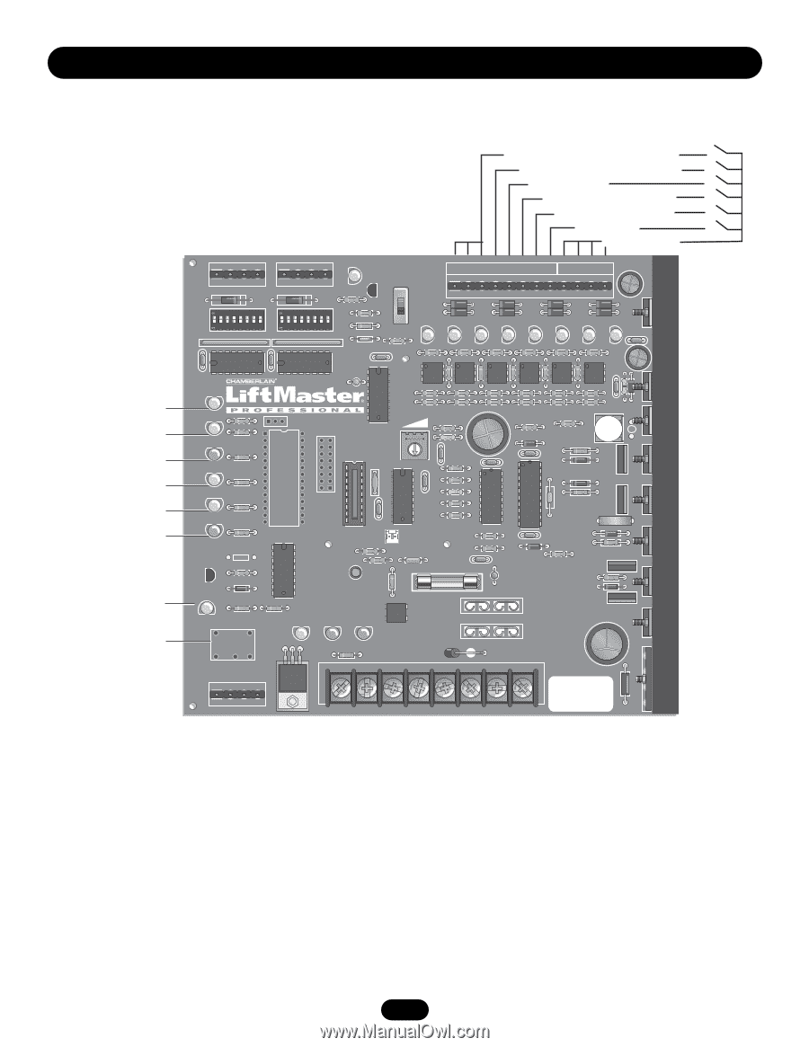
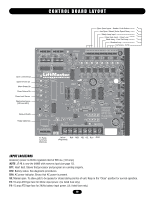
CONTROL BOARD LAYOUT Open Limit Sensor Open Drivers On Motor Brake On Close Drivers On Close Limit Sensor Obstruction Sense (IRD and MRT) Relay Indicator Relay (Optional) Open Gate Inputs - Reader, Push Button Aux Open / Reset (Pulse Open/Close) Safety Loop Input Close Gate Input - Close Loop Back Away - Free Exit Loop Shadow Loop Commons - 0Vdc C18 U18 C15 Q6 Q5 Q4 D28 1 1 J2 AUX LIMITS M/S J3 R14 D8 D1Ø R18 S1 S2 1 2345678 1 2345678 R1 R12 R17 R16 MANUAL Q2 OPEN 1 2 3 4 5 6 7 8 9 1Ø 11 12 J5 S3 T2 T4 T6 T8 T1 T3 T5 T7 OPEN 1 OPEN 2 OPEN 3 AUX 4 SAFETY 5CLOSE 6 BACK 7SHADOW 8 CLOSE R21 C16 D24 D17 R36 D18 R42 D19 R47 D22 R53 D23 D16 D15 C3 R24 R35 R41 R46 R5Ø R61 R3Ø U4 U8 U9 U11 U13 U14 U15 C19 F5 C2 C1 C2 U1 OLS D7 R23 R34 R4Ø R45 R49 R6Ø R22 R33 R39 R44 R48 R59 C22 OPEN X1 D6 R1Ø R9 BRAKE U6 IRD1 R26 R25 R43 R43 D21 R63 U16 R58 D5 R8 U5 C12 U12 D27 CLOSE D4 U7 DX3 C6 U1Ø DX4 X2 C7 R7 D29 CLS D3 R6 R57 C13 R56 IRD D2 U3 R5 U2 R4 C4 CPU R19 JP2 F2 R38 R37 R51 D2Ø DX2 R55 R3 Q1 D9 R2Ø + C5 F1 1A DC C8 C2Ø + R15 D1 + F4 R2 R11 B1 HBEAT BAT LO AC POWER K1 D11 D12 D14 F3 WARNING FOR R62 CONTINUOUS PROTECTION AGAINST FIRE DX1 REPLACE ONLY WITH THE SAME TYPE AND RATING OF FUSE D26 D25 - R13 U19 J4 BAT- MOV MOTOR Aux Relay TR J1 C NC NO DC 1 1 B2 + PWR K1 Relay Terminals (Optional) ACC+ ACC- BAT- BAT+ 24VAC XFMR MOTOR 24Vdc BLK RED YEL YEL BLU ORG (Regulated) INPUT LOCATIONS Accessory power is 24Vdc regulated rated at 500 ma. [1/2 amp]. NOTE: J5 #8 is now the SAMS with memory input (see page 12). D11: Heart beat. Shows that processor and program are running properly. D12: Battery status. See diagnostic procedures. D14: AC power indicator. Shows that AC power is present. S3: Manual open. To allow gate to be opened or closed during service of unit. Keep in the "Close" position for normal operation. F3: 10 amp ATO type fuse for 24Vac input power. (UL listed fuse only.) F4: 15 amp ATO type fuse for 24Vdc battery input power. (UL listed fuse only.) 18
-
 1
1 -
2
-
3
-
4
-
5
-
6
-
7
-
8
-
9
-
10
-
11
-
12
-
 13
13 -
 14
14 -
 15
15 -
 16
16 -
 17
17 -
 18
18 -
 19
19 -
 20
20 -
 21
21 -
 22
22 -
 23
23 -
24
 |
 |