LiftMaster MJ MJ5011E Installation-2008 Manual - Page 10
Power Wiring Chart, Remove Cover, Run Power Wires To Electrical Box - 50
 |
View all LiftMaster MJ manuals
Add to My Manuals
Save this manual to your list of manuals |
Page 10 highlights
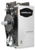
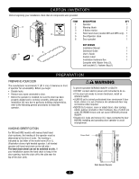
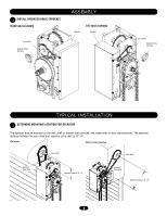
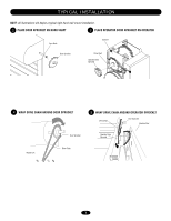
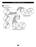
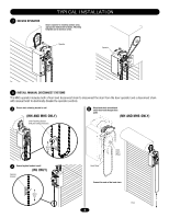
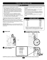
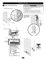
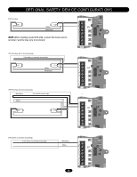
NG WARNING TYPICAL INSTALLATION N WARNING To reduce the risk of SEVERE INJURY or DEATH: • ANY maintenance to the operator or in the area near the operator MUST NOT be performed until disconnecting the electrical power and locking-out the power via the operator power switch. Upon completion of maintenance the area MUST be cleared and secured, at that time the unit may be returned to service. • Disconnect power at the fuse box BEFORE proceeding. Operator MUST be properly grounded and connected in accordance with local electrical codes. The operator should be on a separate fused line of adequate capacity. • ALL electrical connections MUST be made by a qualified individual. • DO NOT install ANY wiring or attempt to run the operator without consulting the wiring diagram. • Reversing devices are recommended for ALL installations. • ALL power wiring should be on a dedicated circuit and well protected. The location of the power disconnect should be visible and clearly labeled. • ALL power and control wiring MUST be run in separate conduit. EMENPTOWER AND GROUND WIRING CONNECTIAONVS ERTISSEMENTPOWER WIRING CHART ON AVERTISSEMENT NOTE: Power and control wiring must be run in separate conduit in accordance with local electrical codes. Must use 14 AWG or heavier wire for power wiring. Use conduit knockouts for wiring as DISTANCE 50' indicated on the electrical box labels. 100' 200' GAUGE 14 AWG 12 AWG 8 AWG* IMPORTANT NOTE: Operator must be properly grounded. Failure to properly ground the operator could result in electric shock and serious injury. 350' 500' 1000' 6 AWG* 4 AWG* 2 AWG* * Maximum wire gauge that can be connected to the operator's terminal is 12 AWG. When a larger wire gauge is required, the wire must be gauged down to 12 AWG. 9 REMOVE COVER 10 RUN POWER WIRES TO ELECTRICAL BOX ACCORDING TO LOCAL ELECTRICAL CODES NCIA ÓN Electrical Box Cover 11 ATTACH POWER AND GROUND WIRES TO TERMINALS ADVERTENCIAElectrical Box Operator ADVERTENCIA Power Sealing Nut (Not Provided) Electrical Box Conduit Ground Neutral Hot Line Power 115 Vac Single Phase Do NOT turn power on until you have finished making ALL power and control wiring connections. 10 Control
-
 1
1 -
2
-
3
-
4
-
 5
5 -
 6
6 -
 7
7 -
 8
8 -
 9
9 -
 10
10 -
 11
11 -
 12
12 -
 13
13 -
 14
14 -
 15
15 -
16
-
17
-
18
-
19
-
20
-
21
-
22
-
23
-
24
-
25
-
26
-
27
-
28
-
29
-
30
-
31
-
32
 |
 |