LiftMaster MJ MJ5011E Installation-2008 Manual - Page 16
Logic Board Layout, DESCRIPTION, FUNCTION
 |
View all LiftMaster MJ manuals
Add to My Manuals
Save this manual to your list of manuals |
Page 16 highlights
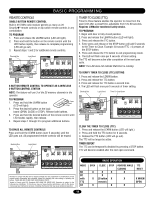
LOGIC BOARD LAYOUT 432 1 5 6 AUX AANUT X ANT ^^^^ 7 TTC LEARN STOP CLOSE OPEN LEDD14 1 2 3 4 5 6 7 LMEP1 LMEP2 COM INTRLK STOP CLOSE OPEN 8 9 10 ITEM 1 2 3 4 5 6 7 8 9 10 DESCRIPTION Open Button Close Button Stop Button Learn Button Timer to Close Button Purple Wire Antenna Auxiliary Antenna Connection LED Field Wiring Terminal Factory Wiring Connector FUNCTION Open Door Close Door Stop Door Programs the remote controls and performs additional programming Programs the Timer to Close Primary Antenna For use with external antenna kit EXT-ANT. Not Provided Used during programming and diagnosing error codes Field wiring connections Factory wiring harness connection 16
-
 1
1 -
2
-
3
-
4
-
5
-
6
-
7
-
8
-
9
-
10
-
 11
11 -
 12
12 -
 13
13 -
 14
14 -
 15
15 -
 16
16 -
 17
17 -
 18
18 -
 19
19 -
 20
20 -
 21
21 -
22
-
23
-
24
-
25
-
26
-
27
-
28
-
29
-
30
-
31
-
32
 |
 |
16
LOGIC BOARD LAYOUT
AUX
^^^^
AUX ANT
D14
COM
INTRLK
STOP
LED
OPEN
CLOSE
TTC
LEARN
1
LMEP1 LMEP2
2
3
4
5
6
7
STOP
CLOSE
OPEN
ITEM
DESCRIPTION
FUNCTION
1
Open Button
Open Door
2
Close Button
Close Door
3
Stop Button
Stop Door
4
Learn Button
Programs the remote controls and
performs additional programming
5
Timer to Close Button
Programs the Timer to Close
6
Purple Wire Antenna
Primary Antenna
7
Auxiliary Antenna Connection
For use with external antenna kit -
EXT-ANT. Not Provided
8
LED
Used during programming and
diagnosing error codes
9
Field Wiring Terminal
Field wiring connections
10
Factory Wiring Connector
Factory wiring harness connection
5
10
9
8
7
6
4
3
2
1